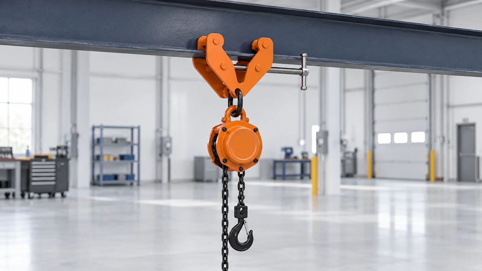
How to Choose a Beam Clamp for Hoist Suspension: Capacity, Beam Fit, Installation and Inspection
A beam clamp can create a convenient suspension point for a manual or powered hoist without drilling or welding the supporting beam. However, selecting one is not as simple as matching the capacity printed on the clamp to the capacity printed on the hoist.
The clamp must fit the actual beam flange, connect correctly to the hoist, carry the complete suspended load and remain suitable for the expected load direction, environment and operating conditions. The supporting beam and its structure must also be capable of carrying all imposed forces.
A clamp that has sufficient nominal capacity but does not fully engage the flange can still be unsuitable. The same applies when a fixed beam clamp is selected for an application that requires horizontal load travel, when a hook bears against its latch, or when side pull occurs outside the clamp manufacturer’s permitted loading directions.
This guide explains how to select a beam clamp for hoist suspension, how it differs from a trolley and a lifting clamp, what information to verify before installation and what to inspect before use.
Quick answer: Select a beam clamp only after confirming the maximum load transferred to its suspension point, the beam flange width and thickness, the beam profile and condition, the required load direction, the hoist connection geometry, available headroom and working environment. Use a beam clamp for a fixed suspension point. If the hoist must travel horizontally along the beam, use a compatible trolley instead. Never assume that a beam clamp permits side loading, angled loading or below-the-hook lifting unless the instructions for that exact model expressly allow it.
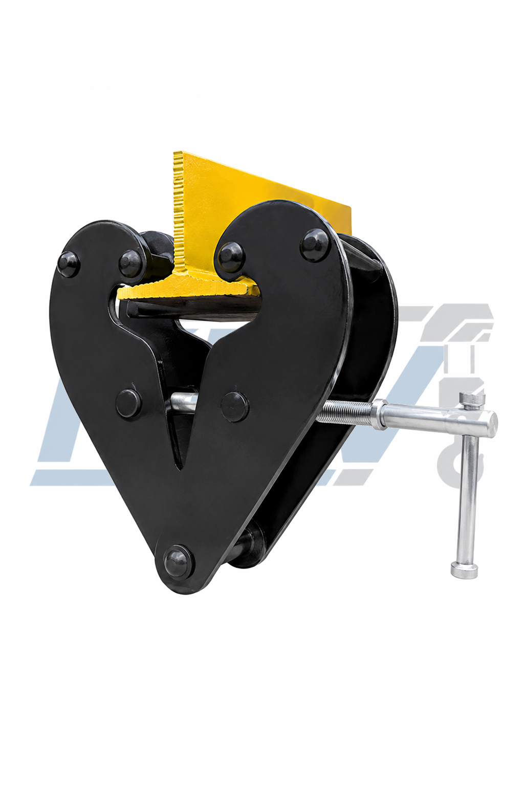
Table of contents
- What is a beam clamp for hoist suspension?
- Decide whether the hoist must remain fixed or travel
- Compare a beam clamp, trolley and lifting clamp
- Check eight selection factors
- Compare the KKV JG range
- Use a six-step selection process
- Plan installation correctly
- Inspect the clamp
- Avoid common mistakes
- Prepare a complete RFQ
- Read the frequently asked questions
What Is a Beam Clamp for Hoist Suspension?
A beam clamp is an adjustable attachment installed on the flange of a compatible structural beam. In a hoist-suspension application, it creates a fixed point from which a hoist or another approved lifting component can be suspended.
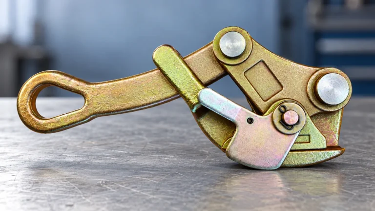
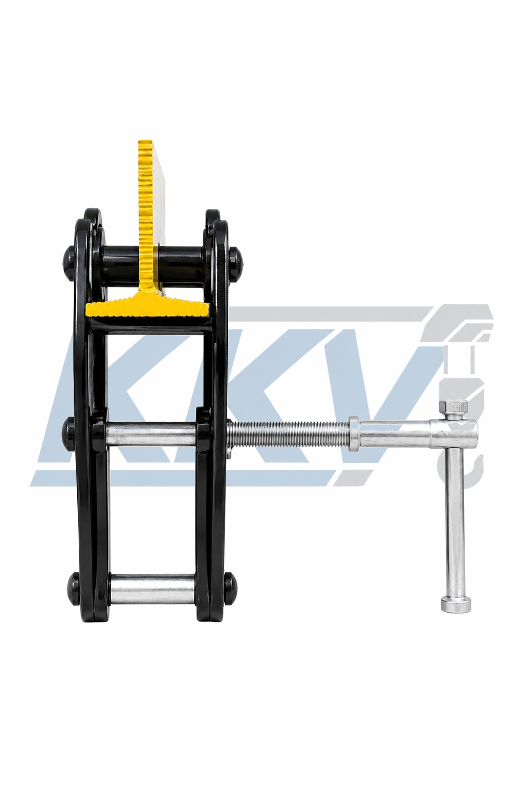
A typical adjustable beam clamp uses a threaded spindle to move its side plates or jaws inward and outward. The clamp is opened sufficiently to pass over the beam flange and is then tightened in accordance with the manufacturer’s instructions. Correct installation requires the intended load-bearing surfaces to engage the flange properly.
The clamp itself does not lift the load. The hoist provides the lifting motion, while the clamp transfers the suspended forces into the beam and supporting structure.
A complete load path may include:
- the supporting building structure;
- the structural beam;
- the beam clamp;
- a suspension pin, shackle or designated attachment point;
- the hoist top hook or suspension connection;
- the hoist body and load chain or wire rope;
- the lower hook, sling and other rigging; and
- the payload.
Every component in this path must be suitable. The capacity of one component does not compensate for inadequate capacity, poor condition or incorrect installation elsewhere in the system.
The KKV JG Adjustable Beam Clamp is described as a removable suspension attachment for selected H-beams and I-beams. It can provide a fixed suspension point for compatible chain blocks, lever hoists and other lifting attachments without drilling or welding the beam.
First Decide Whether the Hoist Must Remain Fixed or Travel
The first selection question is not capacity. It is whether the load needs only vertical lifting at one location or must also move horizontally along the beam.
Choose a beam clamp when:
- the hoist will operate from one fixed suspension point;
- the load can remain vertically aligned beneath that point;
- horizontal movement is unnecessary or will be provided by a separate approved system;
- a removable attachment is preferred over drilling or welding; and
- the beam and structure have been confirmed as suitable for the imposed forces.
Choose a trolley when:
- the hoist must travel along the beam;
- loads must be transferred between work positions;
- the work process requires controlled horizontal positioning; and
- the beam route, flange dimensions and any curves are compatible with the selected trolley.
A plain trolley travels when the suspended system is moved using the method permitted by its operating instructions. A geared trolley uses a hand chain to drive horizontal travel. KKV lists both types in its manual beam trolley range.
For a closer comparison, see Push Trolley vs Geared Trolley: How to Choose by Capacity, Beam Fit and Travel Distance.
Do not attempt to make a fixed beam clamp slide along a beam. Unless the instructions for the exact model and application explicitly state otherwise, the clamp should remain securely positioned. Dragging the load, side-pulling the hoist or using the suspended load to force the clamp along the flange can create unintended loading and loss of secure engagement.
Beam Clamp vs Trolley vs Lifting Clamp
These products may all use the word “clamp” or connect to a beam, but they perform different jobs.
| Equipment | Primary purpose | Position during normal use | Horizontal travel | Key selection question |
|---|---|---|---|---|
| Suspension beam clamp | Creates a fixed hoist suspension point on a compatible beam | Fixed on the supporting beam | No | Does it fit the beam and support the complete suspended load in the permitted direction? |
| Plain trolley | Carries a hoist along a compatible beam | Moves on trolley wheels | Yes, by manual push | Are the beam, capacity and required travel suitable for push operation? |
| Geared trolley | Carries a hoist along a compatible beam | Moves on trolley wheels | Yes, by hand chain | Is controlled horizontal positioning required? |
| Below-the-hook lifting clamp | Grips a beam, plate or other load to be lifted | Attached to the load | Moves with the load | Is the exact load material, shape, thickness, orientation and surface condition approved? |
A suspension beam clamp normally remains on the supporting beam. A below-the-hook lifting clamp grips the item being lifted.
This distinction is important because manufacturer permissions vary. Some clamp models are approved for both suspension and specifically defined below-the-hook applications. Other manufacturers expressly classify their beam clamps as suspension points only. A product’s appearance is not enough to determine its permitted use.
The KKV JG product page describes the JG as a suspension attachment. Do not assume that it can be used to pick up a loose beam, pull at an angle or serve as a horizontal anchor without written confirmation for the exact model and configuration.
Eight Factors to Check Before Selecting a Beam Clamp
1. Maximum Load Transferred to the Suspension Point
Start with the maximum load that may be transferred through the beam clamp, not merely the usual payload.
Depending on the system and the manufacturer’s definition of working load limit, the suspended-load calculation may need to consider:
- maximum payload;
- slings, shackles, lifting beams or other below-the-hook attachments;
- hoist body and suspension components;
- load chain, chain container or other suspended equipment; and
- any additional equipment supported from the same point.
The beam and supporting structure may also need to account for the clamp’s own weight and all applicable force effects. A qualified person or structural engineer should evaluate the support where required.
Do not apply a homemade safety factor to compensate for uncertainty, and do not exceed a rated capacity because the lift is short or infrequent. Obtain the manufacturer’s current capacity definition and select an appropriately rated model.
A hoist and beam clamp carrying the same nominal rating should not automatically be considered compatible. Confirm whether the total suspended system remains within the clamp’s rated limit.
2. Beam Flange Width
Beam clamps have a defined adjustment range. Measure the actual flange at the intended installation point and confirm that it falls within the stated range for the selected model.
Do not select from a nominal beam designation alone. Existing beams may differ from drawings, and coatings, repairs, local damage or manufacturing tolerances may affect the available fit.
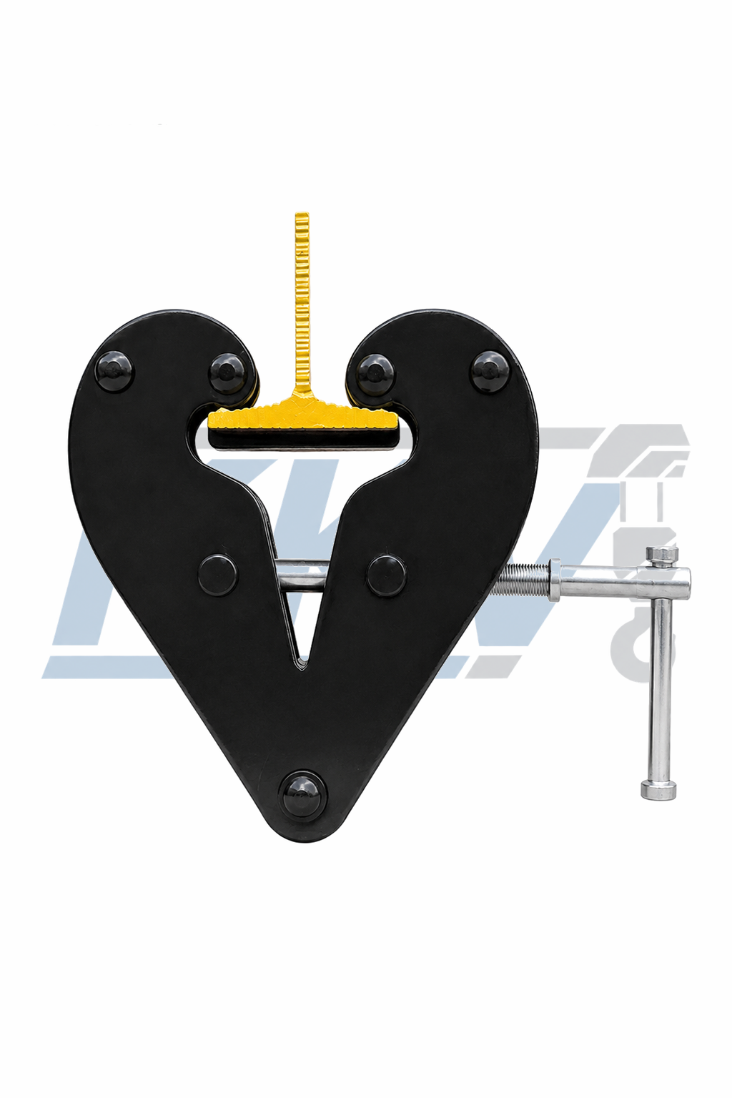
The clamp should not be operated at an apparent fit created by partial jaw contact. The manufacturer’s fitting diagram and instructions determine what correct engagement looks like.
3. Flange Thickness and Beam Profile
Flange width is only one part of beam compatibility. Also verify:
- flange thickness;
- flat or tapered flange profile;
- edge shape and corner radius;
- I-beam, H-beam or other section geometry;
- clearance around web stiffeners, joints and connections;
- surface irregularities, welds or obstructions; and
- whether the clamp jaws can reach their intended bearing surfaces.
A clamp may span the flange width yet still be unsuitable because its jaws cannot seat fully around the flange.
The current KKV JG table publishes applicable beam-width ranges, but final selection should also be checked against the current product drawing and instructions for flange thickness, profile and connection clearance.
4. Beam Strength, Stability and Condition
A beam clamp does not strengthen the beam. The structural beam, its connections and the wider support structure must be suitable for the maximum expected forces at the selected location.
Check for conditions such as:
- visible bending or distortion;
- cracks or damaged welds;
- severe corrosion or section loss;
- local flange damage;
- loose structural connections;
- previous unauthorized drilling or modification;
- obstructions that prevent correct clamp seating; and
- a location too close to an unsupported end or unsuitable connection.
A clamp rating applies to the clamp; it is not proof that the building beam can carry the load. Where beam capacity is unknown, have the supporting structure evaluated by a qualified person before installation.
5. Permitted Load Direction
A fixed hoist suspension point should normally be arranged so the load hangs freely and vertically beneath the intended suspension point.
Do not assume that a beam clamp permits:
- side pull;
- pulling along the beam;
- cross-beam loading;
- angled loading;
- guided or restrained loads;
- load dragging; or
- shock or impact loading.
Manufacturer permissions can differ substantially. One product manual may prohibit side loading, while another specialized clamp may publish defined reductions or angular limits. Those permissions are model-specific and cannot be transferred to the KKV JG or any other clamp.
Unless the exact manual states otherwise, specify a straight, vertical and freely suspended load. If the task requires pulling, tensioning or angular force, give the supplier the magnitude and direction of every force and request written confirmation of a suitable configuration.
6. Hoist and Suspension Connection
The beam clamp’s attachment point must be compatible with the hoist’s top hook, shackle, suspension pin or other approved connection.
Verify:
- attachment-point opening and material diameter;
- hoist hook throat opening;
- free articulation without binding;
- correct seating in the hook saddle;
- adequate clearance from side plates, spindle and beam;
- hook-latch closure;
- prevention of point loading or side loading; and
- compatibility of any intermediate shackle or connector.
The hook should carry the load in its saddle. A hook latch is intended to help retain the connection; it must not support the suspension point or carry the load.
Do not connect a sling, chain or rope around the clamp’s adjustment spindle unless the manufacturer identifies that part as a load-bearing attachment point. Use only the designated suspension connection.
If you are still choosing the hoist, explore KKV manual chain hoists and read the guide on how to choose a manual chain hoist. The HSZ-T Manual Chain Hoist is one available option, but its suspension connection must still be checked against the selected beam clamp.
7. Available Headroom
Headroom is the vertical distance consumed by the suspension system before the hook reaches its highest practical position.
A beam-clamp installation may include:
- clamp depth below the beam;
- suspension bar, pin or shackle;
- hoist top-hook dimensions;
- hoist minimum hook-to-hook distance; and
- required articulation clearance.
Measure from the underside of the beam to the highest required position of the load hook. Compare that space with a current dimensional drawing of the complete clamp-and-hoist assembly.
Do not estimate headroom from a product photograph. Two clamps with the same capacity and beam range may have different suspension geometries.
8. Environment, Documentation and Intended Service
Operating conditions can affect corrosion, lubrication, inspection frequency and material suitability.
Tell the supplier if the clamp will be used in:
- outdoor or wet areas;
- coastal or salt-laden air;
- high-humidity environments;
- acidic, alkaline or chemically aggressive areas;
- galvanizing facilities;
- very low or high temperatures;
- dusty or abrasive conditions;
- potentially explosive atmospheres;
- food, pharmaceutical or clean-process areas; or
- locations involving hazardous materials.
Do not assume a standard clamp is suitable for extreme temperatures, explosive atmospheres, underwater use or corrosive processes.
Also specify the required documentation, such as the current operating manual, dimensional drawing, product identification, inspection or test documents, spare-parts information and any declaration required by the destination market.
Certification and regulatory requirements depend on the destination, application and purchasing specification. They should be confirmed before ordering rather than inferred from a similar product.
KKV JG Adjustable Beam Clamp Range
The current KKV JG Adjustable Beam Clamp page lists four models:
| Model | Rated load listed by KKV | Applicable beam width |
|---|---|---|
| JG-1A | 1 t | 75–208 mm |
| JG-2A | 2 t | 75–208 mm |
| JG-3A | 3 t | 80–320 mm |
| JG-5A | 5 t | 80–320 mm |
The product uses a manual threaded adjustment mechanism and is described for selected H-beams and I-beams. It can provide a removable fixed suspension point without drilling or welding the supporting beam.
The published width range is an initial screening value, not a complete compatibility decision. Before ordering, request or confirm the current drawing and instructions for:
- maximum compatible flange thickness;
- accepted beam-flange profile;
- suspension opening and connection dimensions;
- permitted load direction;
- environmental limits;
- installation and locking procedure;
- inspection and discard criteria; and
- required certificates and documents.
View the complete category of beam clamps for hoists.
A Six-Step Beam Clamp Selection Process
Step 1: Define the Lift and Required Movement
Record what will be lifted, the maximum payload and the required working positions.
Decide whether the hoist will remain at a single point or travel along the beam. If horizontal movement is required, stop the beam-clamp selection and evaluate a trolley or another engineered travel system.
Also state whether the load will always hang vertically and freely. Identify any possibility of side pull, guided motion, tensioning or load dragging.
Step 2: Calculate the Maximum Suspension Load
List every item carried below the clamp. Include the hoist and all relevant rigging and accessories, not only the payload.
Ask the clamp manufacturer or supplier to confirm how its stated rated load applies to the complete suspended assembly. Do not reduce the calculated requirement because the load is lifted only occasionally.
Separately provide the complete imposed load to the person responsible for confirming the beam and structural support.
Step 3: Measure the Actual Beam
Measure and record:
- flange width at the installation point;
- flange thickness;
- beam-section designation, if known;
- flange profile;
- available edge and underside clearance;
- nearby stiffeners, joints, bolts and obstructions; and
- condition of the flange and support structure.
Include clear photographs and a beam drawing when available. A photograph alone should not replace measurements.
Step 4: Check the Hoist Connection and Headroom
Provide the hoist model, rated capacity, top-hook or suspension dimensions and hoist deadweight.
Confirm that the connection can articulate freely, sit in the intended load-bearing area and allow the latch to close without carrying load.
Create a simple vertical stack-up drawing if headroom is limited. Include the beam, clamp, connector, hoist and required upper hook position.
Step 5: Confirm Service and Environmental Conditions
State whether the clamp will be used indoors or outdoors, the operating temperature, humidity and corrosion exposure, typical lifts per shift, expected load spectrum, installation duration, inspection arrangements, destination country and applicable project requirements.
“Occasional use” does not remove the need for proper selection or inspection. Long periods out of service may also require inspection before recommissioning.
Step 6: Obtain Written Configuration Confirmation
Before ordering, confirm the exact beam-clamp model, rated load and unit, beam-width and thickness compatibility, load direction, hoist connection, required locking arrangement, installation instructions, inspection criteria and supplied documentation.
Keep the confirmation, manual and product identification with the equipment records. Avoid purchasing from a table that shows only capacity and beam width when the remaining application details have not been resolved.
General Installation Principles
Important: The following is a planning overview, not a substitute for the installation instructions supplied with the exact clamp. Installation should be performed by trained or qualified personnel in accordance with the manufacturer’s manual, the lifting-system requirements and applicable local regulations.
Before Installation
- Isolate the work area and ensure that no load is supported by the clamp during installation.
- Confirm the beam and structure have been approved for the intended load.
- Match the clamp model and identification to the approved selection.
- Inspect the clamp for damage, missing parts, corrosion, deformation and illegible markings.
- Confirm the spindle, jaws, pins, suspension point and locking components are in serviceable condition.
- Verify the flange measurements and compare them with the approved range.
- Make sure there is safe access for installation and future inspection.
Positioning the Clamp
Open the clamp only as needed to pass its arms or jaws over the flange. Position it at the approved suspension location, clear of obstructions and damaged areas.
Close and tighten it using the manufacturer’s prescribed method. Correctly fitted jaws should engage the intended flange surfaces fully and symmetrically. A visible gap or contact only at the tips of the side plates may indicate incorrect fitting.
Do not:
- hammer the clamp into place;
- add a pipe or extension to the adjustment handle;
- use uncontrolled force to compensate for poor fit;
- weld, drill or modify the clamp;
- grind the beam or clamp to create clearance;
- substitute an unapproved pin, bolt or shackle; or
- install or adjust the clamp while it supports a load.
Use any lock nut, grub screw, retaining device or other securing feature exactly as described in the model-specific instructions. Do not assume every clamp uses the same locking method or tightening force.
Attaching the Hoist
Connect the hoist only to the designated suspension point. Check that:
- the hook is seated in its saddle;
- the latch closes and remains unloaded;
- the connection is not wedged against a side plate;
- the hook, shackle or pin can articulate as intended;
- no component is twisted or side loaded; and
- the hoist hangs vertically beneath the clamp.
After installation, perform the checks and trial operation required by the clamp and hoist manufacturers. Any trial lift should be controlled, with personnel clear of the load and danger zone. Stop if the clamp shifts, the beam deforms, the connection binds or any unusual condition appears.
The Columbus McKinnon YC, SC92 and YRC operating manual illustrates why full jaw engagement, correct load direction and model-specific fitting instructions matter. Its dimensions, tightening instructions and inspection intervals apply to those models, not automatically to a KKV clamp.
Pre-Use and Periodic Inspection
Inspection requirements depend on the exact manufacturer, applicable regulations, service severity and site risk assessment. Do not copy an inspection interval from another brand’s manual.
A practical inspection program normally includes initial, pre-use or every-lift, frequent and periodic checks as required by the applicable instructions.
Pre-Use Check
Before use, verify:
- rated-load marking and identification are present and legible;
- the approved clamp is installed on the correct beam;
- the clamp remains firmly and correctly seated;
- the jaws or side plates fully engage the flange as required;
- there is no visible crack, deformation, severe wear or corrosion;
- the threaded spindle is not bent or visibly damaged;
- threads and moving components operate as intended;
- pins, fasteners, retaining rings and locking parts are present and secure;
- the suspension point is free from cracks, distortion and significant wear;
- the beam shows no new deformation, cracking, local damage or severe corrosion;
- the hoist connection sits correctly in the hook saddle;
- the latch closes but does not carry the load;
- the planned load remains within the approved capacity and direction; and
- the load can move freely without side pull or obstruction.
Detailed or Periodic Check
A competent or qualified person should examine the clamp at the interval required by the manufacturer, regulations and site inspection program.
Items may include:
- functional operation of the adjusting mechanism;
- thread condition and significant wear;
- clamp jaws, arms and side plates;
- suspension bar, pin, shackle or designated connection;
- handles, bushings, spacers and retaining components;
- loose, missing, deformed or corroded fasteners;
- cracks, distortion, wear and corrosion on structural parts;
- condition and legibility of capacity and warning labels;
- evidence of unauthorized repair, welding or modification;
- condition of the supporting beam and surrounding structure; and
- maintenance and inspection records.
Actual discard dimensions and acceptable wear limits must come from the manufacturer. Do not create a general percentage or dimensional limit for all beam clamps.
Remove the clamp from service and refer it to a qualified person if there is uncertainty about its condition, fit, identification or operating behavior. Do not straighten, weld or rebuild a load-bearing component without manufacturer authorization.
Inspection results and approved repairs should be documented. After repair, alteration, long-term storage or a significant incident, follow the manufacturer’s requirements for reinspection and any required testing before returning the clamp to service.
The Harrington Universal Beam Clamp manual is another useful example of model-specific installation and inspection requirements. Always apply the manual supplied for the actual product in service.
Common Beam Clamp Selection and Use Mistakes
Matching Capacity Only
A rated load does not confirm beam fit, connection geometry, load direction or support capacity. Capacity is one part of the selection.
Checking Width but Not Flange Thickness
The jaws may span the flange but fail to seat correctly because the flange is too thick or has an incompatible profile.
Treating a Fixed Clamp as a Trolley
A beam clamp is not a substitute for horizontal travel equipment. Use an approved trolley when movement along the beam is required.
Assuming Side Pull Is Acceptable
Loading-angle permissions differ by model. Unless the exact instructions approve the application, keep the load vertical and freely suspended.
Ignoring Hoist and Rigging Deadweight
The payload is not necessarily the complete load transferred through the suspension point. Confirm the full suspended system and the manufacturer’s working-load definition.
Loading the Hook Latch
The suspension connection must sit in the hook saddle. A latch retains the connection but is not a load-bearing surface.
Using the Adjustment Spindle as an Attachment Point
The spindle is not automatically a suspension bar. Attach the hoist only to the connection identified by the manufacturer.
Using Handle Extensions or Impact Tools
Extra leverage can damage components or create an installation outside the manufacturer’s intended procedure. Use only the specified method and locking arrangement.
Assuming “No Drilling or Welding” Means No Structural Review
A removable clamp still transfers significant forces into the beam. The beam and its support must be assessed for the complete application.
Leaving a Long-Term Installation Unchecked
A clamp that stays in one location still requires inspection. Corrosion, vibration, environmental exposure, beam damage and unauthorized adjustment can develop over time.
Information to Include in Your RFQ
Providing complete application data helps the supplier check more than capacity and reduces the risk of receiving a clamp that cannot fit the actual beam.
| RFQ item | Information to provide |
|---|---|
| Maximum payload | Maximum load at the lower hook and the unit of measure |
| Rigging and attachments | Slings, shackles, lifting beam, fixtures and their weights |
| Hoist | Type, model, capacity, deadweight and top-connection dimensions |
| Required clamp rating | Supplier to confirm from the complete suspended load |
| Beam section | I-beam, H-beam or exact section designation |
| Flange width | Measured value at the installation point |
| Flange thickness | Measured value |
| Beam condition | New or existing, coating, corrosion, damage or obstructions |
| Required movement | Fixed vertical lifting or horizontal travel |
| Load direction | Vertical, angled or other forces clearly identified |
| Headroom | Available distance and required upper hook position |
| Environment | Indoor/outdoor, temperature, humidity, chemicals and corrosion |
| Service | Lifts per shift, typical load and installation duration |
| Documentation | Manual, drawing, test documents, certificates and language |
| Destination | Country and project requirements |
| Supporting files | Beam drawing, hoist drawing and clear site photographs |
Send this information through the KKV contact page and request confirmation of the current model, drawing and supplied documents before placing the order.
Frequently Asked Questions
Can I use a beam clamp with the same nominal capacity as my hoist?
Not automatically. The clamp must carry the load transferred through its suspension point, which may include the hoist and other suspended equipment in addition to the payload. Confirm how the clamp manufacturer defines rated load and whether the complete system remains within that limit. The beam and supporting structure require a separate capacity assessment.
How do I measure a beam for a clamp?
Measure the flange width and thickness at the intended installation point. Record the beam profile, edge shape, nearby obstructions and available clearance. If possible, provide the structural section designation and a drawing. Do not rely only on a nominal beam name or an old drawing.
Is beam-flange width enough to select the clamp?
No. Width determines whether the clamp’s adjustment range may span the flange, but correct fit also depends on flange thickness, profile, jaw geometry and clearance. The suspension connection, load direction, environment and structural capacity must also be verified.
Can a beam clamp fit both I-beams and H-beams?
Some adjustable models are designed for ranges of I-beams and H-beams, including the KKV JG range as described on its product page. However, those terms cover many flange dimensions and profiles. Confirm the exact beam dimensions against the current drawing and instructions for the selected clamp.
Can a beam clamp be side loaded?
Only if the instructions for the exact clamp model expressly permit the proposed direction and force. Manufacturer rules differ, and a side-load permission published for one product cannot be applied to another. For ordinary hoist suspension, arrange the system for a straight, vertical and freely suspended load unless written approval states otherwise.
What is the difference between a beam clamp and a beam trolley?
A beam clamp normally creates a fixed suspension point. A trolley supports the hoist on wheels and allows it to move along a compatible beam. Choose a clamp for lifting at one location. Choose a plain, geared or powered trolley when horizontal load travel is part of the job.
Can I use a suspension beam clamp to lift a loose steel beam?
Do not assume so. A suspension clamp is selected to attach a hoist to a supporting beam. A below-the-hook beam or plate clamp is selected to grip a load being lifted. Some manufacturers approve specific multi-purpose models, while others expressly prohibit using their suspension clamps as lifting devices. Follow the exact product classification and manual.
Can a beam clamp be left installed permanently?
Some manufacturers describe certain clamps as suitable for temporary or longer-term mounting, but “permanent” does not mean maintenance-free. The beam, installation, environment and inspection program must remain suitable. Confirm the intended installation duration with the supplier and continue all required inspections.
How often should a beam clamp be inspected?
Inspect it before use as required by the applicable operating procedure. More detailed inspection intervals depend on the manufacturer’s instructions, service severity, environment, site risk assessment and local regulations. Do not apply another manufacturer’s calendar interval without checking the manual for your clamp.
What should I send a supplier before requesting a quotation?
Send the maximum payload, hoist model and deadweight, all suspended accessories, beam flange width and thickness, beam profile, required movement, load direction, headroom, environment, service frequency, destination and document requirements. A beam drawing, hoist drawing and clear photographs of the installation area are especially useful.
Choose the Suspension System, Not Just the Clamp
A suitable beam-clamp installation is the result of matching the complete load path. The clamp must have adequate rated capacity, fit the actual flange, connect correctly to the hoist and remain within its approved load direction and operating environment. The supporting beam and structure must also be capable of accepting the resulting forces.
Use a fixed beam clamp when the hoist should remain in one position. Use a compatible trolley when the process requires horizontal travel. Never assume that a suspension clamp can lift a loose beam, accept side pull or work in an extreme environment without model-specific approval.
KKV currently lists JG models from 1 t to 5 t with published beam-width ranges from 75 mm to 320 mm. To identify the correct configuration, send KKV your beam dimensions, complete suspended-load information, hoist connection, operating conditions and required documents.
For help selecting a beam clamp: Contact KKV with your application data and request confirmation of the exact model, current drawing and documentation.
Safety note: This guide supports product selection and quotation preparation. It does not replace the clamp manufacturer’s operating manual, structural assessment, site lifting plan, competent-person inspection or applicable regulations. Never exceed the rated load, modify load-bearing parts without authorization, lift people or allow anyone beneath a suspended load.
Technical References
- KKV JG Adjustable Beam Clamp product and specification page
- Columbus McKinnon YC, SC92 and YRC Beam Clamp Operating Manual
- Harrington Universal Beam Clamp Owner’s Manual
- Tiger Lifting BCF Beam Clamp Technical Sheet
Manufacturer manuals describe different intended uses, environmental limits, loading directions and inspection programs. Their model-specific permissions demonstrate why these details must be verified; they are not specifications for the KKV JG range.