Chain Rigging
KKV Grade 80 Chain Sling Assemblies can be configured for single-leg, multi-leg and endless lifting arrangements using compatible chain, master links, coupling components, shortening devices and end fittings. Select the complete assembly by load, center of gravity, chain size, number of legs, hitch type, included angle, required reach, environment and documentation.
- Current reference table covers chain sizes from 6 mm to 32 mm.
- Single-leg, 2–4-leg and endless configurations are available subject to exact assembly confirmation.
- The complete sling WLL is limited by its lowest-rated component and actual configuration.
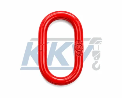
- Master links, coupling links, chain, shortening devices and hooks must be mutually compatible.
- Send the required load, leg count, angle, reach and end-fitting details for quotation.
Description
Grade 80 Chain Sling Assemblies
KKV chain sling assemblies provide configurable lifting connections for loads that require one or more chain legs, a compatible top connection and application-specific end fittings.
Each assembly must be selected as a complete system. Chain diameter or grade alone does not determine capacity. The total load, center of gravity, number of load-bearing legs, hitch type, included angle, load distribution, reach, end fittings, shortening arrangement, environment and required documentation all affect the final configuration.
Configured Around the Complete Lifting Task
Multiple Leg Options
Single-leg, two-leg, three-leg, four-leg and endless arrangements can be considered according to the load and lifting points.
Chain Size Range
The current KKV reference includes nominal chain sizes from 6 mm to 32 mm; exact availability must be confirmed with the selected assembly.
Matched Components
Master links, chain, coupling links, shortening devices and hooks must match the chain grade, size and connection geometry.
Angle-Based Selection
Multi-leg capacity depends on the actual sling angle and load distribution, not only the number of legs attached to the load.
Required Reach
Leg length and effective reach can be specified for the lifting points, while adjustment requires an approved compatible shortening method.
Order Documentation
Identification, drawings, inspection records, certificates, packaging and destination requirements should be agreed before production.
Capacity Belongs to the Complete Configuration
The Working Load Limit (WLL) applies to the identified complete sling assembly in its approved configuration. It must not exceed the rating of the lowest-rated component. Changing a hook, shortening device, master link, number of legs, hitch or angle can change the allowable load.
Do not treat a four-leg sling as four times the capacity of one leg. Not every attached leg necessarily shares the load equally. Confirm the governing table, tag, drawing and supplied documentation for the exact assembly before lifting.
Choose the Sling Arrangement from the Load
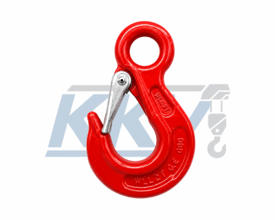
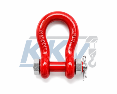
Review KKV Grade 80 lifting chain, D shackles with safety bolts and eye sling hooks with latches when defining the assembly. Products shown on the same website are not automatically compatible; every connection and rating must be confirmed.
Six Checks Before Ordering a Chain Sling
Define the Load
Provide maximum weight, dimensions, center of gravity, lifting-point locations and whether the load can shift.
Select the Configuration
State the number of legs, hitch type, included angle and how many legs are expected to carry load.
Confirm Chain Size and WLL
Use the configuration-specific WLL, identification and current technical data; do not infer capacity from diameter alone.
Specify Reach and Adjustment
Provide effective reach for each leg and identify any approved shortening requirement without knots or makeshift fasteners.
Match Every Connection
Confirm master-link, coupling-link, chain, shortener, hook and lifting-point dimensions and ratings.
Confirm Service and Documents
Describe temperature, corrosion, chemicals, duty, destination, marking, certificate and packaging requirements.
Chain Sling Applications
Use Only an Approved Compatible Shortening Method
Never shorten a chain sling with knots, twisting, bolts, wire or makeshift fasteners. Where adjustable reach is required, use a shortening component confirmed for the chain grade, chain size and sling design, and apply any model-specific capacity rule supplied for that component.
Keep chain links correctly seated and free from twist. Do not force an oversized chain link or fitting into a connection, and do not mix unidentified components from different systems simply because they appear to fit.
Inspect the Whole Assembly, Not Only the Chain
Remove the sling from service if identification is missing or illegible, damage is found, the assembly has been altered, or continued safe use is uncertain. Inspection frequency and removal criteria must follow the supplied instructions, applicable regulations, service severity and site procedures.
Send the Complete Lifting Requirement
Provide load weight, center of gravity, leg count, hitch, included angle, chain size, reach, end fittings, environment, quantity, destination and required documents.
Additional information
| Chain Size | 6–32mm |
|---|---|
| Sling Configuration | n Legs |
| Working Load Limit | 0.95–56.8T |
Chain Sling Working Load Limit Reference
Compare the existing KKV page values by chain size, number of legs, sling arrangement and angle. Final selection must be confirmed for the exact supplied assembly.
| Chain Size (mm) |
Single-Leg Slings | 2, 3 or 4-Leg Straight Slings | 2, 3 or 4-Leg Reeved Slings | Endless Basket Slings | Endless Reeved |
||||||||
|---|---|---|---|---|---|---|---|---|---|---|---|---|---|
| Straight | Adjustable | Reeved | 60° | 90° | 120° | 60° | 90° | 120° | 60° | 90° | 120° | ||
| 6.0 | 1.2 | 1.2 | 0.95 | 2.2 | 1.7 | 1.2 | 1.6 | 1.3 | 0.95 | 1.6 | 1.3 | 0.95 | 1.9 |
| 7.1 | 1.6 | 1.6 | 1.2 | 2.8 | 2.3 | 1.6 | 2.1 | 1.7 | 1.2 | 2.1 | 1.7 | 1.2 | 2.4 |
| 8.0 | 2.0 | 2.0 | 1.5 | 3.5 | 2.8 | 2.0 | 2.6 | 2.1 | 1.5 | 2.6 | 2.1 | 1.5 | 3.0 |
| 10.0 | 3.2 | 3.2 | 2.4 | 5.5 | 4.5 | 3.2 | 4.1 | 3.4 | 2.4 | 4.1 | 3.4 | 2.4 | 4.8 |
| 13.0 | 5.4 | 5.4 | 4.0 | 9.4 | 7.6 | 5.4 | 7.0 | 5.7 | 4.0 | 7.0 | 5.7 | 4.0 | 8.1 |
| 16.0 | 8.0 | 8.0* | 6.0 | 13.8 | 11.3 | 8.0 | 10.4 | 8.5 | 6.0 | 10.4 | 8.5 | 6.0 | 12.0 |
| 20.0 | 12.5 | 12.5* | 9.4 | 21.6 | 17.6 | 12.5 | 16.3 | 13.3 | 9.4 | 16.3 | 13.3 | 9.4 | 18.8 |
| 22.0 | 15.5 | 11.6* | 11.6 | 26.8 | 21.9 | 15.5 | 20.1 | 16.4 | 11.6 | 20.1 | 16.4 | 11.6 | 23.2 |
| 26.0 | 21.6 | 16.2* | 16.2 | 37.4 | 30.5 | 21.6 | 28.0 | 22.9 | 16.2 | 28.0 | 22.9 | 16.2 | 32.4 |
| 32.0 | 32.8 | 24.6* | 24.6 | 56.8 | 46.4 | 32.8 | 42.6 | 34.8 | 24.6 | 42.6 | 34.8 | 24.6 | 49.2 |
Selection requirement: Do not exceed the WLL shown on the identification and current configuration-specific documentation. The complete assembly is limited by its lowest-rated compatible component and actual load distribution.