Push Trolley vs Geared Trolley: How to Choose by Capacity, Beam Fit and Travel Distance
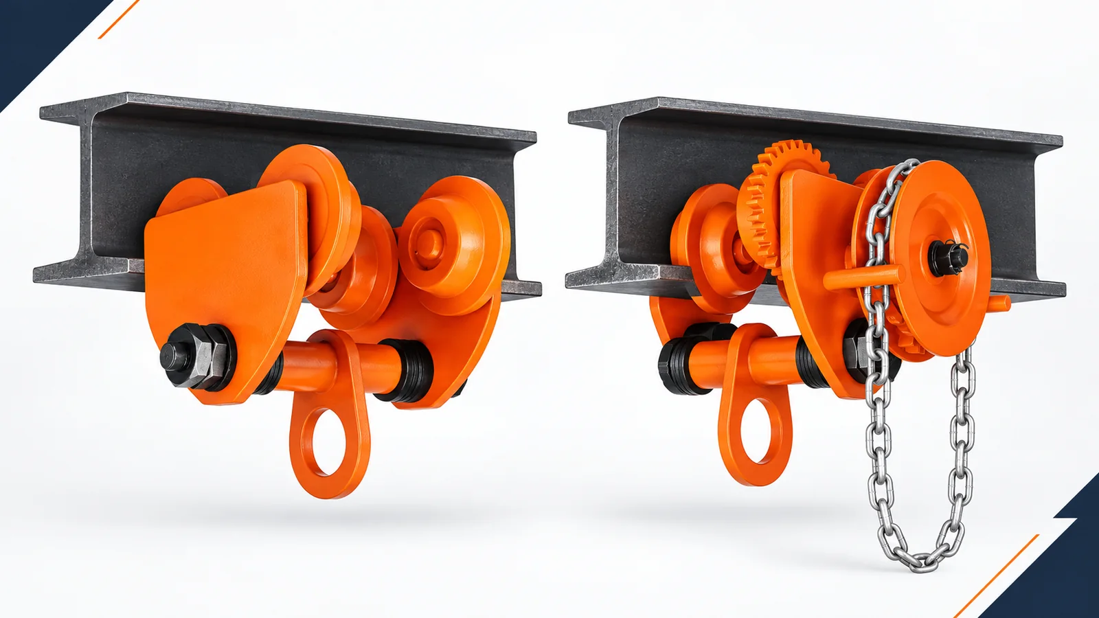
A push trolley and a geared trolley both let a suspended hoist travel along a suitable beam, but they do not give the operator the same control method. A push trolley is moved through direct manual force using the method permitted by its manufacturer. A geared trolley uses a hand-chain loop to turn a geared wheel system and move the trolley along the runway.
The better choice is not decided by price, capacity or travel distance alone. It depends on the complete suspended load, the exact beam flange, wheel compatibility, available headroom, operator access, required positioning control, route geometry, work frequency and environment. The supporting beam, end stops, hoist, trolley and attachments must work as one rated system.
This guide explains what to measure, what documents to request and how to compare the current KKV GCT plain-trolley and GCL geared-trolley families without relying on a rule of thumb.
Quick answer: Choose a push trolley when direct manual movement is permitted, the operator can control the load safely from an approved position, and the verified starting effort, travel and positioning needs suit the application. Choose a geared trolley when hand-chain operation provides a more practical operating position or more deliberate travel control. In both cases, confirm the exact trolley’s rated capacity, beam flange width and thickness, wheel profile, adjustment method, minimum curve radius, headroom, hoist connection, environment and inspection requirements. Never assume a geared trolley is a brake, a push trolley is suitable for every long runway, or a catalogue capacity proves that the trolley fits the beam.
Table of contents
- Understand the two trolley types
- Compare push and geared trolleys at a glance
- Calculate capacity from the complete suspended load
- Verify beam flange fit and wheel compatibility
- Evaluate travel distance and operator access
- Compare positioning control and operating effort
- Check straight beams, curves and end stops
- Confirm headroom, suspension and the load path
- Match duty and environment
- Compare KKV trolley series
- Use a six-step trolley selection process
- Prepare a complete trolley RFQ
- Install and inspect before use
- Avoid common selection mistakes
- Frequently asked questions
Understand the Two Trolley Types
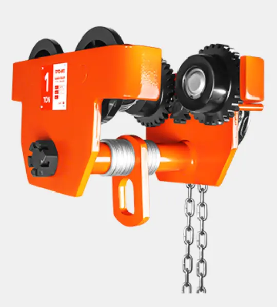
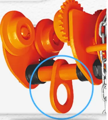
Both types normally use flanged wheels and adjustable side plates to run on a compatible beam. A suspension eye or lug connects the trolley to a hoist or other approved equipment. Their main difference is how horizontal movement is produced.
What is a push trolley?
A push trolley, also called a plain trolley, has no hand-chain gear drive. The operator applies force using the procedure allowed by the product manual. Depending on the manufacturer and model, that may mean controlling the suspended load, the hoist or another approved point. Instructions are not universal: some manufacturers permit a push or pull method that another manufacturer specifically prohibits. The selected trolley’s manual must therefore define how it is moved.
The simple construction can reduce components, hanging hand chain and maintenance points. It can be attractive for occasional transfers, accessible runways and loads that move with acceptable manual effort. Simplicity does not make the trolley suitable for every beam or every load. A heavily loaded trolley, high mounting position, poor wheel-to-beam fit, misaligned runway or difficult operator position can make direct movement impractical or unsafe.
What is a geared trolley?
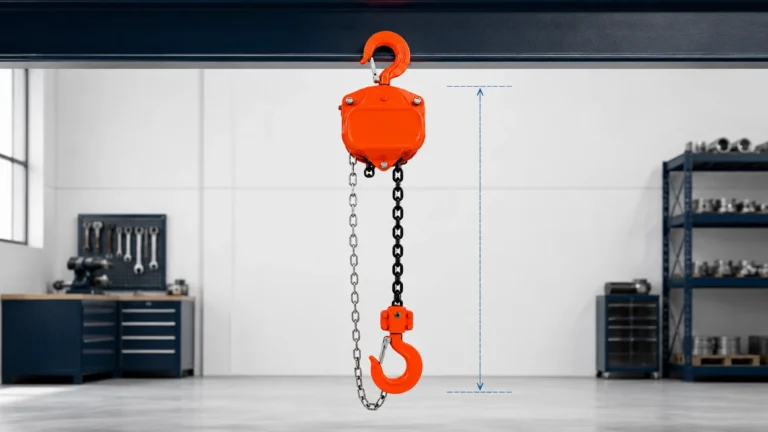
A geared trolley has an endless hand chain that turns a hand wheel, gear train and driven trolley wheel. The operator pulls the hand chain from below rather than applying direct force at the suspended load or hoist. This can provide more deliberate travel and can make the operating position more practical on higher beams or with heavier arrangements.
The gear drive does not automatically make the trolley a brake, a load-holding device or suitable for a sloping runway. A geared trolley can still move if forces act on the system, and any parking lock is a separate, model-specific feature. The hand chain also needs a clear operating path and a suitable length. It must not interfere with the load chain, electrical cables, structure or operator route.
The Harrington TF2/TS2 trolley manual and current KITO plain and geared pages illustrate these concepts. Their dimensions and adjustment values do not transfer to a KKV trolley.
Compare Push and Geared Trolleys at a Glance
The table is a screening tool. A final choice still requires the exact model manual, trolley drawing, beam information and application review.
| Selection point | Push or plain trolley | Geared trolley | What must be verified |
|---|---|---|---|
| Travel input | Direct manual force using the manufacturer-approved method | Endless hand chain drives the trolley through gearing | Approved operating method, operator position and required force |
| Positioning | Simple direct movement; control depends strongly on load, access and runway condition | More deliberate incremental movement is often possible | Required approach accuracy, stopping behaviour and load-swing control |
| Operator access | Operator must reach and control the approved push point safely | Operator works from the hand-chain position | Chain length, clear pull path, floor access and obstructions |
| Hardware | No traverse hand-chain or gear drive | Adds hand chain, hand wheel, gears and driven wheel | Inspection, lubrication, entanglement and replacement-part requirements |
| Typical reason to shortlist | Simplicity and direct movement for a verified, accessible duty | Controlled hand-chain travel or a more practical operating position | Complete task, not a universal distance or capacity threshold |
| Beam requirements | Exact flange, wheel and adjustment limits apply | Exact flange, wheel and adjustment limits apply | Beam width, thickness, profile, radius, level, alignment and end stops |
| Holding on a slope | Not implied | Not implied by gearing | A specifically approved gradient, drive and holding arrangement |
| Final approval | Exact trolley plus hoist and support system | Exact trolley plus hoist and support system | Manufacturer documents and applicable site rules |
These are comparisons, not guarantees. Stopping response, swing and effort still depend on the load, operator, wheels, adjustment, runway and product design.
Calculate Capacity from the Complete Suspended Load
The trolley supports more than the payload. Start with the maximum total load that will act through the trolley suspension point. Depending on the arrangement, this can include:
- the payload, container and packaging;
- slings, shackles, lifting beam, clamp, magnet or other below-the-hook equipment;
- the complete hoist, load chain, lower hook block and chain container;
- the trolley-hung suspension components and approved attachments;
- any other mass that the manufacturer requires to be included.
Compare that total with the rated capacity shown for the exact trolley. Do not subtract the hoist weight from a guessed capacity allowance or assume the trolley and hoist have identical ratings because they are sold together. If a hoist is mounted on a higher-capacity trolley, the lower applicable capacity still limits the system. The beam, supporting structure, connections and other components must also be adequate for the loads and effects defined by the responsible engineer and applicable requirements.
Rated capacity is not permission to create side pull, shock load or an off-center suspension. Keep the trolley and hoist vertically over the intended pick point before lifting. Pulling a suspended load sideways can introduce swing, wheel loading and forces that were not part of a simple vertical capacity comparison.
Capacity units also require attention. A supplier may use metric tonnes, kilograms, short tons or another convention. Write both the number and unit in the RFQ and purchase order. For a mixed international project, ask the supplier to confirm the nameplate unit and rated capacity in the destination documentation.
| Application input | Record this value | Why it matters | Evidence to request |
|---|---|---|---|
| Maximum payload | Weight and unit | Forms only part of the trolley load | Weighing record or controlled calculation |
| Hoist and lifting gear | Individual and combined mass | Must be included where suspended from the trolley | Approved product data and rigging list |
| Required trolley capacity | Selected rating and unit | Must cover the applicable complete load | Nameplate, model data and quotation |
| Beam and support | Material, section, span and support details | Must carry the complete system and applicable forces | Structural approval by a competent responsible party |
| Load geometry | Center of gravity and connection layout | Affects vertical alignment and potential side loading | Drawing or application sketch |
Do not add an arbitrary percentage or treat design factor as overload allowance. Select within published ratings; any dynamic allowance or special load case must come from the governing design basis and qualified review.
Verify Beam Flange Fit and Wheel Compatibility
Beam fit is the most common reason a capacity-only selection fails. Two beams with similar nominal depth can have different flange widths, flange thicknesses, taper and edge geometry. A trolley may fit one and be unsuitable for the other.
Measure the actual runway at several locations, especially at joints, transitions and worn areas. Record:
- beam designation and material, if known;
- actual lower-flange width;
- flange thickness and whether the running surface is parallel or tapered;
- flange-edge and root geometry relevant to the wheels;
- runway straightness, level, joints, welds, damage and surface condition;
- any curves, switches, splice plates, end stops or obstructions.
The trolley wheels must have a tread and flange arrangement compatible with the selected beam profile. Wheel flanges guide the trolley; they are not evidence that any I-beam will work. Side-plate spacing, adjustment washers or collars set the installed relationship between the wheels and beam. Too little clearance can cause binding, high effort and wear. Too much can produce poor tracking and, in an extreme mismatch, loss of secure engagement.
Do not copy an air-gap value from another brand. Manufacturer instructions use different measuring references and adjustment methods. For example, the Harrington manual and the Yale HTP/HTG literature both specify their own installation checks, but those values belong to their products. For KKV, ask for the correct washer or collar sequence, allowable flange range and acceptance clearance for the exact model and beam.
Beam width alone is still insufficient. Send a beam cross-section or dimensioned photograph showing width and thickness. If the beam profile is unusual, tapered, worn or locally fabricated, ask KKV to confirm wheel compatibility in writing. If the runway is already installed, measure the full travel path rather than one convenient end.
Evaluate Travel Distance and Operator Access
Travel distance influences selection, but it is only one part of the duty. A short transfer with limited access may favour geared operation, while a longer, lightly loaded and freely accessible runway may be practical with a plain trolley. The opposite may also occur because load, height, floor access, obstacles, wheel condition and cycle rate change the operator’s task.
Record the horizontal distance for one movement, movements per hour, hours per shift, typical and maximum suspended load, and how frequently fine alignment is needed. Walk the operator route and identify columns, machines, guardrails, stored materials, floor edges and pedestrian crossings. The operator must be able to move with the equipment without standing beneath the load or entering a crush zone.
For a push trolley, identify exactly where force may be applied. Never encourage pulling on a load chain, electrical pendant cable or another component that is not an approved traverse control. For a geared trolley, measure the beam height and specify the required hand-chain operating level. A chain loop that is too short, too long or positioned behind an obstruction can defeat the intended advantage.
Harrington, for example, associates its plain trolley with longer traversing and its geared trolley with shorter, precise movements. Treat that as product-family guidance, not a universal distance threshold.
When distances, loads or cycle rates create excessive manual effort, compare an approved powered trolley or complete electric travelling hoist instead of forcing a manual option. Review the KKV electric hoist range together with the electric hoist selection guide when powered lifting or travel may better match the duty.
Compare Positioning Control and Operating Effort
Positioning means more than moving slowly. The operator must start travel, approach the destination, stop without unacceptable swing and align the hook or load with the work. Runway level, wheel bearings, adjustment, suspended height and the load’s center of gravity all affect the response.
A geared trolley often supports incremental movement because the operator can take controlled pulls on the hand chain. It can also keep the operator’s hands away from the trolley body on a high beam. However, gearing does not cancel inertia. A long suspended load can still swing, and a descending or out-of-level runway can still create movement. Do not describe the gearing as a service brake unless the product documentation identifies and rates an actual braking device.
A push trolley provides direct feedback and avoids a traverse hand chain. It may be quicker to reposition in a suitable light-duty arrangement. But direct force can become awkward when the load is heavy, the suspension is high or the push point is difficult to reach. Excessive effort can also be a warning of incorrect adjustment, beam damage, contamination, bearing problems or an overloaded system; it should not simply be overcome by jerking the load.
If manual effort matters, request operating information and consider a controlled acceptance trial on the actual runway. Marketing terms such as easy travel are not application data.
Check Straight Beams, Curves and End Stops
Even a straight runway needs aligned joints, suitable running surfaces, clear wheel travel and secure end stops. End stops are a final boundary, not a routine brake.
Curved runways need additional verification. Minimum curve radius varies by trolley series, capacity, wheelbase, adjustment and beam. A trolley that fits the flange on a straight section may bind or lose acceptable wheel contact on a curve. Do not widen the trolley beyond its instructed setting in an attempt to negotiate a tighter radius.
There is no reliable rule that a geared trolley always turns more tightly than a push trolley. Current paired product tables from some manufacturers publish the same minimum radius for their corresponding plain and geared models, while other ranges vary by size. Request the value for the exact selected trolley and beam, then compare it with the tightest measured centerline radius on the route.
Runway gradient is equally model-specific. Neither direct push nor gearing proves that a manual trolley can be used on an incline or hold position when released. If the beam is not level, disclose the measured longitudinal gradient and do not proceed without explicit manufacturer and engineering approval for the complete arrangement.
Before use, traverse the unloaded trolley slowly through the full path, then follow the manufacturer’s commissioning and test requirements.
Confirm Headroom, Suspension and the Load Path
Headroom is the vertical distance consumed by the complete trolley-and-hoist arrangement. It affects the highest hook position and usable lift. Do not compare trolley body height in isolation. Obtain a dimensioned assembly drawing showing the beam, wheels, trolley suspension, hoist top connection, hoist body and upper and lower hook positions.
A hook-mounted hoist may hang lower than an integrated or lug-mounted arrangement. Connection geometry, fasteners and orientation must be expressly compatible. Never modify the suspension to gain headroom without written authorization.
Measure required lift separately from the lowest pick point to the highest hook position, including clearance to lift the load free. Verify usable travel after the trolley and suspension consume building height.
KKV’s manual chain hoist category and trolley category should be reviewed together when preparing a manual travelling-hoist system. Use the manual chain hoist selection guide to define lift and hoist headroom, then confirm the exact suspension combination and assembled dimensions.
The beam, supports, structure, end stops, hoist, hook, slings and attachment point must all be suitable. Trolley selection cannot approve the building structure.
Match Duty and Environment
Manual trolleys still have duty limitations. Record cycles, travel, load spectrum and operating hours rather than describing the job only as occasional or heavy duty. A trolley moved 30 times during one maintenance shutdown creates a different task from a trolley moved every few minutes over multiple shifts.
The environment can change friction, corrosion, lubrication, inspection and material requirements. Tell the supplier about:
- indoor or outdoor installation and weather exposure;
- salt, marine air, fertilizer, chemicals or corrosive cleaning agents;
- dust, abrasive particles, foundry scale or construction debris;
- low or high temperature and rapid temperature change;
- washdown, food, clean-room or hygiene requirements;
- hazardous-area classification or possible explosive atmosphere;
- unusual radiation, vacuum or other special service.
Do not assume a painted standard trolley is approved for outdoor, corrosive or explosive service. Some manufacturers offer corrosion-resistant or spark-resistant variants precisely because standard products do not cover those environments. Coating appearance alone does not establish suitability.
Inspection frequency and lubrication also depend on service and environment. Salt, moisture, contamination and frequent operation may require a more conservative program. Use the exact manufacturer’s manual and the rules applicable at the destination. ASME B30.17 addresses cranes and monorails within its scope, while ASME B30.16 covers relevant hoists. The applicable framework must be determined for the complete installation and jurisdiction.
Compare KKV Trolley Series
The current KKV trolley category shows two plain families and two geared families. The table below describes the purchasing distinction visible on the current product pages. It does not convert a website summary into approval for a particular beam or application.
| KKV series | Travel type | Page-presented distinction | Confirm before ordering |
|---|---|---|---|
| GCT-A Plain Trolley | Direct manual plain-trolley travel | Adjustable trolley construction presented for beam-mounted manual travel | Exact capacity, beam profile, flange width and thickness, spacer sequence, clearance, radius and suspension |
| GCT-B Plain Trolley | Direct manual plain-trolley travel | Alternative plain-trolley family with its own construction and product imagery | Differences from GCT-A, wheel/bearing design, anti-drop features if included, dimensions and exact application limits |
| GCL-A Geared Trolley | Hand-chain geared travel | Hand-chain drive and adjustable beam-width arrangement | Hand-chain length, operating pull, gearing, exact beam setting, radius, headroom and suspension |
| GCL-B Geared Trolley | Hand-chain geared travel | Alternative geared family presented with adjustable spacer construction | Differences from GCL-A, bearing and anti-drop configuration if included, chain specification and exact application limits |
KKV’s current pages present a shared capacity-by-size table across these families. Use it for preliminary screening only; confirm that the selected row applies to the exact A/B and plain/geared configuration.
For the final quotation, request a current exact-model drawing stating beam range and profile, adjustment, minimum radius, dimensions, mass, suspension and applicable hand-chain data. Resolve discrepancies before purchase.
GCL does not mean stronger and GCT does not prove easier. Match the exact model to the measured beam and task.
Use a Six-Step Trolley Selection Process
Step 1: Define the load and complete task
Record the maximum payload, lifting attachments, hoist mass, trolley-hung components, pick and set points, lift height and horizontal travel. Identify the center of gravity, load dimensions and whether accurate alignment is required. State whether the trolley will normally be unloaded or loaded during travel.
Step 2: Survey the complete runway
Record the beam designation and measure lower-flange width and thickness at several positions. Note profile, taper, joints, curves, minimum radius, level, length, end stops, obstructions and access. Obtain confirmation that the supporting structure is suitable for the intended system.
Step 3: Choose the operating concept
Compare approved direct manual movement with hand-chain geared travel. Consider operator position, reachable control height, obstacles, positioning accuracy, travel frequency and expected manual effort. If neither is practical, evaluate a suitable powered travelling arrangement.
Step 4: Match an exact trolley and hoist combination
Select capacity using the complete applicable suspended load. Verify wheel and beam compatibility, flange range, adjustment method, radius, headroom and suspension connection. Confirm how the hoist attaches and whether any special lug, pin or adapter is required.
Step 5: Review duty, environment and destination requirements
State cycles, load spectrum, shifts, temperature, moisture, corrosion, dust, outdoor exposure and hazardous-area classification. Define required manuals, labels, declarations, certificates, inspection records and language. Confirm parts and service availability.
Step 6: Approve documents before shipment
Review the final model code, drawing, data sheet, nameplate information and accessories. Ensure the beam setting, hand-chain length and hoist configuration match the order. Plan installation, commissioning, testing, operator instruction and inspection with qualified personnel.
A beam photo and desired tonnage are not enough for a responsible quotation.
Prepare a Complete Trolley RFQ
A clear request for quotation reduces follow-up and makes competing offers easier to compare. Send dimensions with units and attach a beam cross-section, runway layout and site photographs where possible.
| RFQ field | Example format | Supplier confirmation required |
|---|---|---|
| Maximum complete suspended load | 1,780 kg including hoist and rigging | Rated capacity and unit for exact trolley |
| Hoist | Model, capacity, mass, top suspension and lift | Approved trolley connection and assembled headroom |
| Beam | Section name plus measured flange width and thickness | Compatible wheel profile and adjustment range |
| Runway | Length, straight/curved, tightest radius and measured gradient | Approved route, minimum radius and level limits |
| Operation | Push/plain or geared under consideration | Manufacturer-approved movement method and operating pull information |
| Control height | Beam elevation and desired hand-chain level | Supplied hand-chain length for geared trolley |
| Duty | Moves/hour, distance/move, hours/shift and load spectrum | Suitability for the declared service |
| Environment | Indoor/outdoor, temperature, moisture, dust and chemicals | Coating, materials, exclusions and maintenance requirements |
| Documentation | Destination, language, standards and certificates | Manuals, declarations, test documents and labels supplied |
| Delivery | Quantity, destination, spare parts and deadline | Final model code, accessories, package and lead time |
Request a dimensioned arrangement showing wheel spacing, suspension and headroom. For geared models, add hand-chain size and loop length; for curves, add the approved radius at the selected setting.
Avoid vague entries such as standard I-beam, normal temperature or occasional use.
Install and Inspect Before Use
Installation should be carried out by competent, authorized personnel using the exact trolley and hoist instructions. The supporting structure and runway must already be approved for the intended service. Do not improvise an installation by removing safety features, mixing unapproved fasteners or changing wheel spacing without the specified adjustment components.
Before release for service, verify at least the following within the manufacturer and site procedure:
- model, rated capacity and identification are legible and match the approved documents;
- trolley capacity is suitable for the complete load and is not used to increase a lower hoist or system rating;
- wheels, side plates, suspension member, pins, nuts, washers, collars and locking devices are present and correctly assembled;
- installed wheel spacing and clearance match the exact manual and measured beam;
- wheels sit correctly on the running surface without obvious binding, skew or abnormal contact;
- geared trolley hand chain is correctly reeved, untwisted, undamaged and clear of other chains and structures;
- the hoist connection is approved, correctly oriented and secured;
- runway joints, curves, clearances and end stops are complete and suitable;
- the full path is clear and the operator route avoids suspended-load, pinch and crush zones;
- required commissioning inspection, operational test and load test are completed and recorded by the responsible persons.
During a pre-use check, look for damage, deformation, cracks, missing parts, loose hardware, unusual wheel wear, contamination, corrosion and abnormal noise or effort. The related manual chain hoist inspection checklist covers the hoist-side checks. Move the trolley slowly through the approved test path and stop for binding, abnormal tracking, flange climbing, contact or unexpected force.
Do not use an end stop as a brake. Avoid shock, swing and side pull; keep people clear. Remove a defective trolley from service under the site’s control procedure.
Avoid Common Selection Mistakes
Choosing by payload alone
The trolley also carries the hoist and applicable rigging. Add the complete suspended arrangement and verify every component’s rating.
Measuring only flange width
Wheel tread, flange thickness, profile, taper and installed clearance also determine compatibility. Send a cross-section and measured dimensions.
Assuming geared means braked
Gearing helps produce travel; it does not automatically hold the trolley on a slope. Treat braking, locking and gradient approval as separate product requirements.
Using travel distance as the only decision
There is no universal number at which push must become geared. Combine distance with load, height, access, frequency, positioning and operating effort.
Treating catalogue ranges as installation approval
A family table helps shortlist a size. The exact model drawing, beam setting, radius and suspension still need confirmation.
Ignoring hand-chain clearance
A geared trolley needs the correct chain length and an unobstructed pull path. Check interaction with the load chain, pendant, structure and floor-level equipment.
Forgetting curves and end stops
Measure the tightest curve and inspect the entire route. Fit approved end stops before operation, but do not use them as normal stopping devices.
Trying to overcome high effort with shock
Jerking a load can create swing and shock. Unexpected effort should trigger a check for overload, incorrect adjustment, damaged runway, contamination, misalignment or trolley defects.
Assuming all four KKV website tables are independent
The current shared values require model-level confirmation. Put the exact GCT-A, GCT-B, GCL-A or GCL-B designation and requested capacity on the quotation and drawing.
Frequently Asked Questions
What is the main difference between a push trolley and a geared trolley?
A push trolley uses direct manual force by the manufacturer-approved method. A geared trolley uses an endless hand chain and gear drive. Both still require exact capacity, beam, radius, headroom and service verification.
Is a geared trolley safer than a push trolley?
Not automatically. Either can be suitable when correctly selected and used. Safety depends on the application, access, load control, runway and instructions. Gearing alone does not provide a brake or approve an incline.
Is a push trolley always better for long travel?
No universal distance rule applies. Manufacturer recommendations are product-specific, while load, height, frequency, beam condition and operator access can change the result. Evaluate the exact task and model.
Does a geared trolley hold its position when the hand chain is released?
Do not assume so. Traverse gearing is not automatically a holding brake. Specify any parking, locking or non-level use separately and obtain written approval.
Can the trolley capacity equal the payload weight?
Only if the complete suspended load remains within every rating. Add the hoist, applicable rigging and attachments. The lowest rating in the load path limits the system.
How do I know whether a trolley fits my I-beam?
Measure flange width and thickness and identify the profile. Verify the trolley’s flange range, wheel tread, spacer arrangement, installed clearance, curves, joints and full path.
Can I use adjustment washers from another trolley model?
No, unless expressly approved for the exact model. Washers, collars, pins, nuts and locks form part of the assembly; mixing them can create incorrect wheel engagement.
Can a manual trolley run on a curved beam?
Only when the exact trolley, capacity, beam and setting are approved for the actual curve. Minimum radius is model-specific; verify the tightest curve and commissioning procedure.
Can a push or geared trolley run on an inclined beam?
Do not assume it can. Disclose the measured gradient and obtain explicit approval for the trolley, drive, holding method and complete system.
How long should the geared trolley hand chain be?
The loop should be at a safe operating height and clear of chains, equipment, floor and structure. Specify beam height and operating level; use the approved size and length.
Can I attach any chain hoist to a trolley with the same capacity?
No. Connection, orientation, dimensions, assembled headroom and ratings must be compatible. Obtain exact-combination approval instead of modifying a hook, lug or trolley plate.
When should I consider a powered trolley instead?
Consider powered travel when load, distance, frequency, positioning, access or ergonomics make manual movement impractical. Provide full duty and site data; no universal threshold applies.
Choose the Travel Method Only After Verifying the System
The practical push trolley vs geared trolley decision starts with the task and measured runway. Define the complete suspended load, beam profile, travel route, operator position, headroom, suspension, duty and environment. Then compare the exact GCT or GCL model documents rather than relying on a generic tonnage label.
For trolley selection support, email sales@kkvhoist.com with your maximum complete load, hoist model and mass, beam cross-section and flange measurements, runway length and radius, beam height, required hand-chain level, duty, environment and destination. KKV can then confirm an appropriate product configuration and the documents required for your quotation.
Safety note: This guide supports preliminary product selection and RFQ preparation. It does not replace the trolley, hoist or runway manufacturer’s instructions, structural approval, a site-specific risk assessment, applicable regulations, competent installation, commissioning, inspection or training. Stop using equipment that is damaged, incorrectly adjusted or behaving abnormally, and have it assessed by authorized qualified personnel.