
SJ-A Mechanical Jack
The SJ-A Mechanical Jack is a manually operated lifting jack designed for reliable lifting, positioning and supporting work in industrial maintenance, heavy equipment handling and structural installation. It features a self-locking ratchet mechanism, a reinforced steel body, a grooved top saddle and a low lifting toe for versatile lifting applications.
- Self-locking ratchet device for controlled lifting and safer operation.
- Reinforced steel construction for durability and resistance to deformation.
- Top saddle and low lifting toe for different lifting positions.
- Collapsible handle design for convenient transport and storage.
- Suitable for equipment maintenance, installation, repair and positioning work.
Description
SY-C Mechanical Jack for Heavy Equipment Lifting and Positioning
The SY-C Mechanical Jack is a manually operated lifting
device designed for raising, supporting and positioning heavy machinery
and industrial equipment where dependable mechanical lifting is required.
Its upright mechanical structure combines a manual ratchet drive,
reinforced lifting body, upper lifting saddle, low lifting toe and
stable supporting base into one compact lifting unit.
With no electric motor, battery or hydraulic power unit required,
the SY-C Mechanical Jack is suitable for workshops, machinery
installation, industrial maintenance, construction work and field
applications where simple manual operation is preferred.
Practical Mechanical Lifting Without External Power
The SY-C series combines straightforward manual operation with
practical structural features for industrial lifting, adjustment
and positioning work.
Mechanical Ratchet Drive
Manual ratchet operation converts handle movement into
controlled vertical lifting without electrical or hydraulic power.
Reinforced Upright Structure
The rigid vertical body supports the lifting mechanism and
provides a compact structure for heavy equipment lifting.
Dual Lifting Positions
The upper saddle and lower lifting toe provide alternative
contact positions for different machinery and load geometries.
Collapsible Operating Handle
The manual handle provides operating leverage while its compact
arrangement makes transport and storage more convenient.
Four Models from 5T to 20T
The SY-C Mechanical Jack series includes four rated-capacity options.
All listed models provide 300 mm operating travel,
while lifting-height range and operating force vary according to model.
SY-C5.0
5T rated capacity
300 mm travel
25–725 mm lifting height
SY-C10
10T rated capacity
300 mm travel
30–800 mm lifting height
SY-C16
16T rated capacity
300 mm travel
40–800 mm lifting height
SY-C20
20T rated capacity
300 mm travel
40–860 mm lifting height
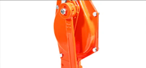
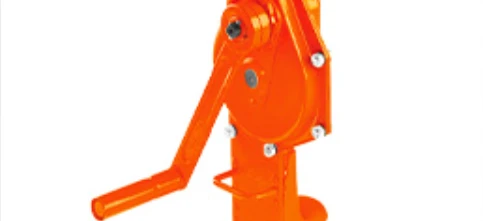
SY-C Mechanical Jack Structural Details
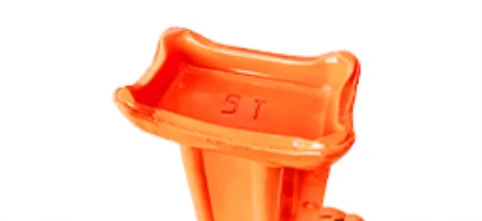
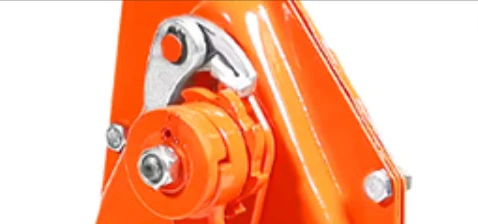
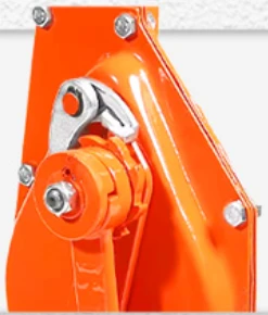
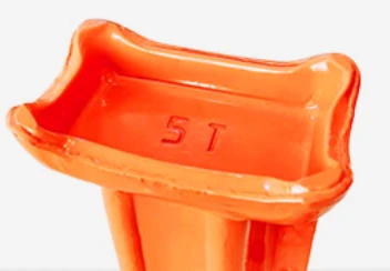
A closer look at the ratchet mechanism, upright jack body,
upper lifting saddle, lower lifting toe and supporting structure
of the SY-C Mechanical Jack.
Practical Details for Manual Mechanical Lifting
Key components are designed around controlled manual lifting,
different load-contact positions and convenient operation in
industrial maintenance environments.
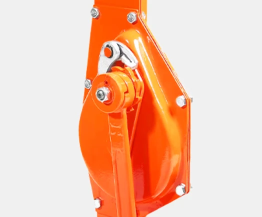
01
Self-Locking Ratchet Device
The mechanical ratchet structure supports controlled,
step-by-step lifting and helps maintain consistent manual
movement during load positioning.
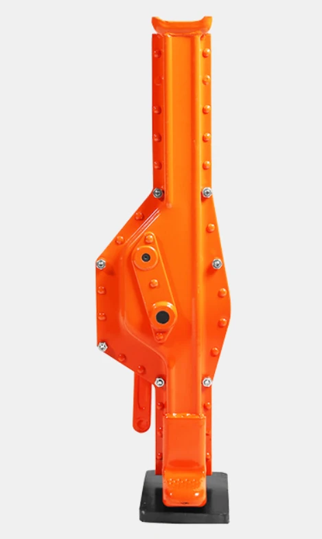
02
Reinforced Grooved Top Saddle
The shaped upper saddle provides a defined contact area
for lifting and supporting suitable loads from the upper
lifting position.
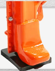
03
Reinforced Low Lifting Toe
The lower lifting point provides an alternative contact
position for machinery and equipment where available
bottom clearance is limited.
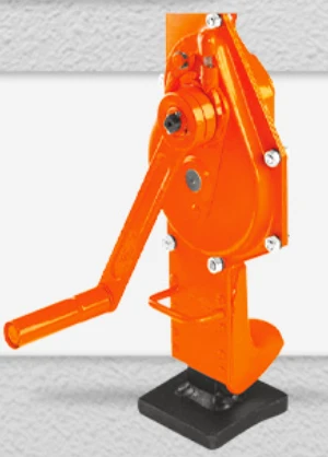
04
Collapsible Operating Handle
The manual handle provides practical leverage during
operation while helping reduce required transport and
storage space.
Top and Low-Position Lifting in One Jack
Different lifting points make the SY-C Mechanical Jack suitable
for a wider range of machinery positioning and maintenance tasks.
01
Top saddle provides an upper lifting and supporting position.
02
Low lifting toe provides access where bottom clearance is limited.
03
Upright structure allows controlled vertical mechanical travel.
04
Broad base provides a stable supporting footprint when correctly positioned.
Details Designed for Daily Industrial Lifting
The following details highlight important areas of the jack’s
structure and manual operating system.
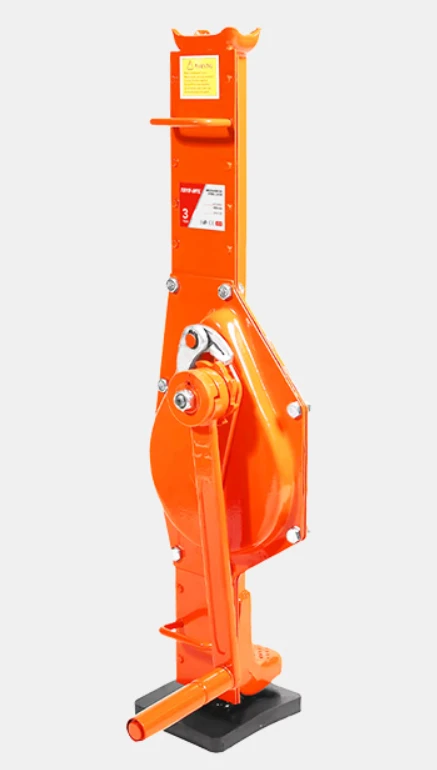
01
Reinforced Body Structure
The rigid upright structure supports the mechanical
lifting assembly and provides a compact load-bearing design.
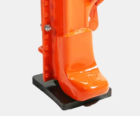
02
Compact Manual Handle
Manual crank operation requires no electric drive,
battery or hydraulic pumping system.
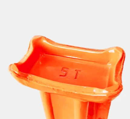
03
Grooved Top Saddle
The shaped upper contact surface provides a defined
lifting position for suitable loads.
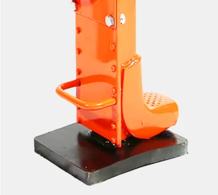
04
Mechanical Ratchet Control
The ratchet drive converts manual handle movement into
controlled vertical travel of the lifting structure.
Where Is the SY-C Mechanical Jack Used?
The SY-C Mechanical Jack is intended for manual lifting and
positioning tasks where compact equipment and independent
mechanical operation are useful.
Machinery Installation
Controlled lifting and positioning during machinery
installation, adjustment and alignment work.
Industrial Maintenance
Temporary lifting and supporting during machinery
inspection, servicing and repair work.
Construction Work
Manual positioning of suitable heavy components during
installation and construction operations.
Railway Maintenance
Portable mechanical lifting for suitable railway,
infrastructure and maintenance tasks.
A Self-Contained Lifting Solution Without External Power
Because the lifting action is produced mechanically through the
operating handle and ratchet structure, the SY-C Mechanical Jack
does not rely on electrical supply or hydraulic pressure.
This makes it particularly useful for workshops, field maintenance,
temporary installation work and locations where access to powered
lifting equipment may be limited.
How to Select the Right SY-C Mechanical Jack
Select the appropriate model according to the maximum load,
required working height, lifting position and operating environment.
01
Confirm Rated Capacity
Select from the listed 5T, 10T, 16T and 20T models
according to the required load capacity.
02
Check Lifting Height
Compare the required working position with the lifting-height
range shown for each model in the Specifications tab.
03
Choose the Lifting Point
Determine whether the application requires use of the
upper saddle or lower lifting toe.
04
Confirm Available Working Space
Ensure sufficient room is available for correct jack
positioning and operating-handle movement.
05
Check Supporting Surface
Position the jack on a stable supporting surface suitable
for the intended lifting operation.
SY-C Mechanical Jack Model Series
SY-C5.0
5T rated capacity
280 N full-load hand force
29.5 kg net weight
SY-C10
10T rated capacity
560 N full-load hand force
50 kg net weight
SY-C16
16T rated capacity
640 N full-load hand force
69 kg net weight
SY-C20
20T rated capacity
640 N full-load hand force
80 kg net weight
Check the Mechanical Jack Before Lifting
Before every lifting operation, confirm that the selected jack,
lifting point, load and supporting surface are suitable for the task.
✓
Confirm that the selected model has sufficient rated capacity.
✓
Inspect the upright jack body for visible damage or deformation.
✓
Check ratchet and operating-handle movement before lifting.
✓
Inspect the upper saddle and lower lifting toe before use.
✓
Position the jack on a stable and appropriate supporting surface.
✓
Keep the load correctly aligned with the intended lifting position.
Routine Checks for Reliable Mechanical Lifting
Jack Body
Inspect the upright body and structural parts for visible
damage, deformation or abnormal wear.
Ratchet Mechanism
Confirm that the ratchet mechanism operates correctly
before the jack is placed under load.
Lifting Points
Check the upper saddle and lower lifting toe for visible
wear, damage or deformation.
Operating Handle
Inspect the handle and connection area and confirm that
manual movement is unobstructed.
Supporting Base
Check the base condition before positioning the jack
on the working surface.
Storage
Keep the jack clean and store it in a dry environment
when not in use.
Need Help Selecting the Right Mechanical Jack?
Compare rated capacity, lifting-height range, hand force,
lifting position and overall dimensions before selecting
the appropriate SY-C Mechanical Jack for your application.
Coming Soon
Additional information
| Rated Capacity | 5–20T |
|---|---|
| Travel | 300mm |
| Lifting Height Range | 25–860mm |
SY-C Series Mechanical Jack Specifications
Compare rated capacity, test load, operating force, lifting range, product weight and overall dimensions across the available SY-C mechanical jack models.
| Model | Rated Capacity | Test Load |
Full-Load Hand Force |
Travel |
Lifting Height Range |
Net Weight |
Overall Dimensions L × W × H |
|---|---|---|---|---|---|---|---|
| SY-C5.0 | 5.0 t | 61.3 kN | 280 N | 300 mm | 25–725 mm | 29.5 kg | 75 × 21 × 25 cm |
| SY-C10 | 10 t | 122.5 kN | 560 N | 300 mm | 30–800 mm | 50 kg | 82 × 27 × 31 cm |
| SY-C16 | 16 t | 196 kN | 640 N | 300 mm | 40–800 mm | 69 kg | 85 × 29 × 35 cm |
| SY-C20 | 20 t | 245 kN | 640 N | 300 mm | 40–860 mm | 80 kg | 90 × 38 × 30 cm |