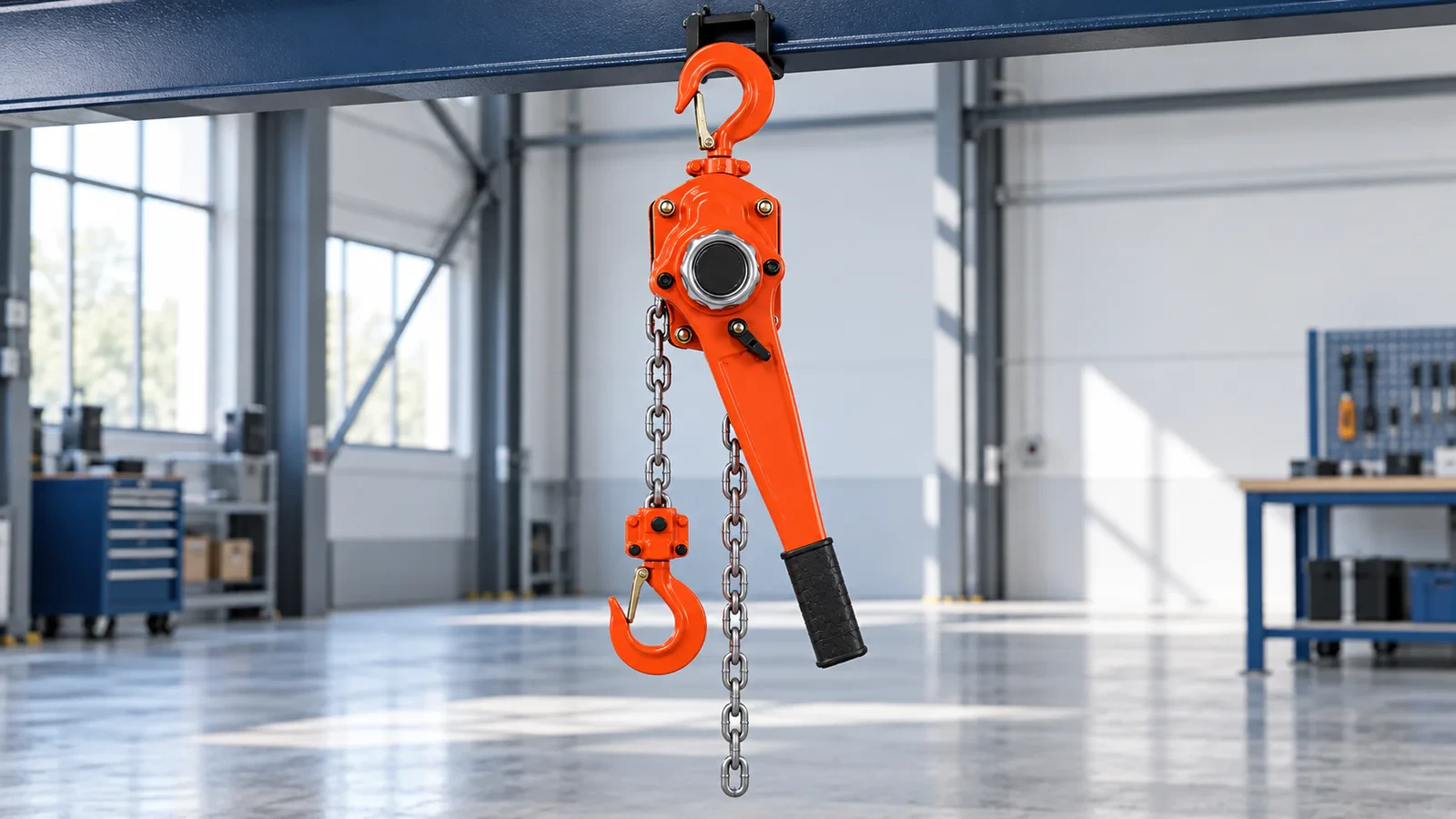
How to Choose a Lever Hoist: Capacity, Lift, Handle Pull and Safety
Choosing a lever hoist requires more than matching the weight of an object to a capacity printed on a nameplate. The correct hoist must be approved for the intended lifting, pulling, positioning or tensioning task, and it must provide enough travel while fitting the available hook-to-hook and handle operating space.
This guide explains how to choose a lever hoist by checking rated capacity, maximum load or line force, lift, headroom, rated-load handle pull, load direction, attachment points, operating frequency, environment and documentation. The hoist, anchors, rigging and supporting structure must be evaluated as one load path.
Quick answer: First define whether the task is vertical lifting, pulling, positioning or tensioning, and verify that the exact lever-hoist model permits that application and direction. Then select a rated capacity that is not below the maximum force applied through the hoist. Confirm lift, minimum closed hook-to-hook distance, full handle sweep, rated-load handle pull, chain and hook arrangement, both attachment points, environment and required documents. Never use a proof-load value, handle extension or overload device as additional working capacity.
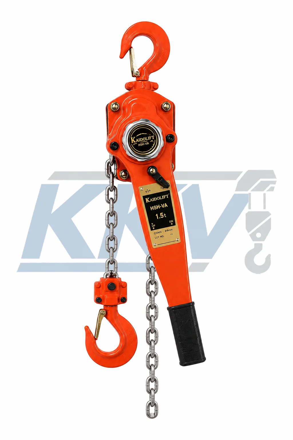
Table of contents
- What is a lever hoist?
- When should you choose one?
- Confirm the required function before sizing
- Nine lever hoist selection factors
- Lift, headroom and handle clearance explained
- Worked selection example
- Application starting points
- Comparing KKV lever hoist series
- A seven-step selection process
- Lever hoist specification checklist
- Common mistakes
- Safety and pre-use inspection
- Frequently asked questions
What Is a Lever Hoist?
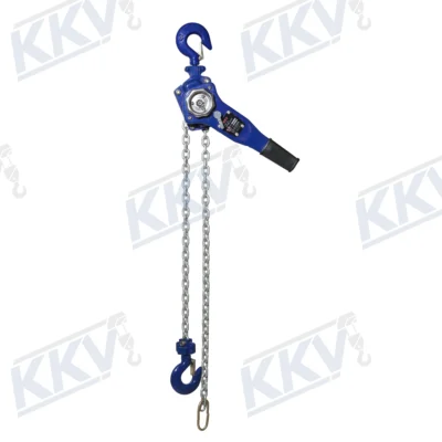
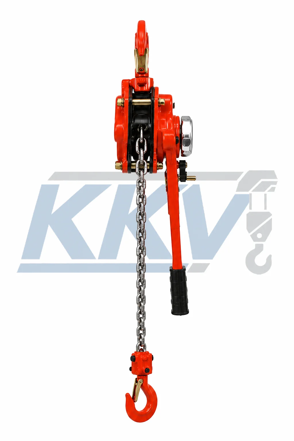
A lever hoist is a compact manual device that moves a load through a reciprocating operating handle, internal gearing, a brake, calibrated load chain and upper and lower hooks. It may also be called a lever block, ratchet lever hoist or chain puller.
The operator selects the permitted direction and moves the handle through repeated strokes. The mechanism advances the load chain incrementally, allowing controlled short-distance lifting or positioning without electrical or pneumatic power. Exact control arrangements differ, so the product manual—not a generic sequence—must govern operation.
The term come-along is not precise. It may describe a chain lever hoist, a wire-rope pulling tool or another lever-operated device. A purchase request should identify the mechanism, rated function and exact model rather than relying on this informal name.
Rated capacity, rated-load handle pull and lift are three different specifications. Capacity limits the load applied through the hoist, handle pull describes operator effort under stated conditions, and lift describes available hook travel.
When Should You Choose a Lever Hoist?
A lever hoist can be a useful starting point when the application needs:
- portable manual equipment with no external power supply;
- controlled movement over a relatively short distance;
- machinery or pipe alignment between suitable attachment points;
- lifting, pulling or tensioning in a direction permitted by the exact model;
- close incremental positioning during erection or maintenance;
- a compact body where an overhead hand-chain loop would be inconvenient;
- temporary work at approved anchors rather than a permanent powered installation.
A compact body does not automatically make the hoist suitable for a confined space. The handle still needs a usable stroke, the operator needs secure footing, and the hoist must be able to align with the load path without the body, chain or hooks binding against surrounding steelwork.
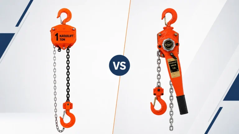
For a primarily vertical lift with longer travel from a fixed overhead point, start with the manual chain hoist selection guide. If you are still deciding between the two manual designs, read Manual Chain Hoist vs Lever Hoist. For frequent cycles, long travel or production work, compare the electric hoist selection guide.
Confirm the Required Function Before Sizing
The first question is not “How many tonnes?” It is “What must the hoist do?” Record the required function before comparing products.
Vertical Lifting
For vertical lifting, the lever hoist raises a freely suspended material load. Add the payload and every below-the-hook item, including slings, shackles, clamps, lifting beams and fixtures. The load chain and both hooks must align with the direction of loading, and personnel must remain clear of the suspended load and its path.
Pulling and Positioning
For horizontal or angled positioning, object mass is not the same as required line pull. Friction, slope, wheel or skid condition, initial breakaway, obstacles, acceleration and geometry all affect the force applied through the hoist. A qualified person should calculate or establish the maximum line force and verify both anchors and every connection.
Horizontal operation does not increase a lever hoist’s rated capacity. The exact model must permit the intended orientation, and “multi-directional use” must never be interpreted as permission to side-load a hook or trap the hoist body against a structure.
Tensioning
A lever hoist can apply and hold tension only when the exact product and procedure permit it. The operator’s impression of handle resistance is not a reliable force measurement. If the task needs a specified tension, use an approved method and suitable measuring equipment, such as a calibrated load cell, rather than treating the hoist as a scale.
Tasks Requiring Separate Approval
Do not assume that an ordinary material-handling lever hoist is approved for lifting people, transporting people, vehicle recovery, towing, cargo restraint, guided loads, permanent support or work on energized equipment. These tasks can involve different equipment, standards and hazards.
How to Choose a Lever Hoist: Nine Selection Factors
1. Rated Capacity and Maximum Applied Force
Use the rated capacity and units shown for the exact model. Product documents may use rated load, rated capacity, working load limit (WLL) or safe working load (SWL). A metric tonne is 1,000 kg and is not the same as a US short ton, so confirm the unit rather than relying on the word “ton.”
For vertical lifting, select a capacity not lower than the maximum payload plus all attachments carried by the lower hook. The hoist’s own weight is not part of the lower-hook load, but it must be included when the upper support and complete structural load path are assessed.
For pulling or tensioning, select from the maximum line force—not from the object’s mass alone. Do not apply an arbitrary percentage because a force is unknown. Determine the load through calculation, measurement or qualified engineering review.
Proof load, test load, minimum breaking force and design factor are not working capacity. An overload indicator or load limiter does not increase the rated load and must not be used to estimate an unknown force.
2. Required Lift, Reach and Chain Take-Up
Lift is the usable travel of the load hook between its operating limits. In pulling work, the same specification may be described informally as reach or take-up, but the product’s defined lift and allowable chain travel still control.
Record the starting distance between attachment points, the final distance and the movement required. Add only the installation and landing clearance justified by the job. A longer chain adds weight and loose chain that must be managed safely; it does not increase capacity.
Never run the mechanism beyond the permitted chain travel or use an end fitting as a routine travel stop. If the required travel is long, compare the number of handle strokes and operator effort before choosing a manual solution.
3. Minimum Closed Length and Headroom
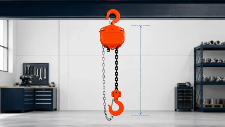
The minimum closed length is commonly the shortest distance between the bearing points of the upper and lower hooks when the hoist is fully taken up. For vertical lifting, this dimension determines the headroom consumed above the highest load-hook position.
Use the dimensional drawing for the selected capacity. Body dimensions, hook blocks, chain falls and closed length can change within the same product series. Measure the space at the most restricted point rather than assuming that a compact-looking body will fit.
4. Rated-Load Handle Pull and Operating Stroke
Rated-load handle pull is the force required at the operating handle under stated rated-load conditions. It is a force value, commonly expressed in N or daN, not simply a weight in kg. Compare the exact published value for the selected capacity and configuration.
Lower handle pull may reduce operator effort, but it does not necessarily mean faster travel. Gearing, efficiency, chain falls, handle length, load and chain movement all affect how the product feels and how many strokes are needed.
Never extend the handle with a pipe or cheater bar, strike it with a tool, connect a powered driver or use several people on one handle. Abnormally high effort is a reason to stop and check for overload, poor alignment, obstruction, chain problems or equipment damage.
5. Handle Sweep, Hand Clearance and Operator Position
Measure more than the hoist body. The handle must complete an effective stroke without hitting a beam, wall, machine, rigging or the operator’s body. Include clearance for the operator’s hand and fingers, selector access and the small movement the hoist may make as it aligns with the load.
The operator needs stable footing and a clear view. Position the operator away from a suspended load, pinch points, the loaded line and the potential snap-back path if a pulling system or attachment fails.
6. Load Direction, Hook Loading and Alignment
Use a lever hoist horizontally or at an angle only when the exact manual permits that application. The upper hook, hoist body, chain and lower hook must form the intended line of pull. Do not side-load the hook, force the body against an obstruction or route chain around a corner.
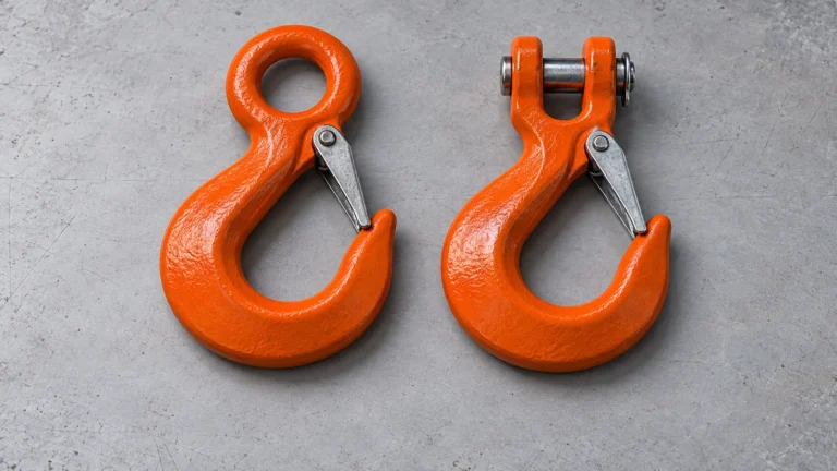
Rigging must bear in the hook bowl. A hook latch helps retain slack rigging; it is not a load-bearing component. Do not apply load to the hook tip or latch, and do not use the load chain as a sling around the object.
7. Suspension, Anchors and the Complete Load Path
Both attachment points must be suitable for the maximum force and its actual direction. Check pad eyes, beams, clamps, shackles, slings, fixtures, foundations and structural connections. Pulling arrangements can introduce horizontal, uplift or angled forces that an anchor designed only for a vertical load may not resist.
Do not assume two hoists will share a load equally. Small differences in geometry, stiffness and operation can create unequal forces. A multi-hoist lift or pull requires an engineered procedure, suitable coordination and verified load distribution.
8. Load Chain, Hooks, Free Chaining and Options
Lever-hoist load chain is calibrated to the chain wheel’s pitch and pocket geometry. Ordinary Grade 80 sling chain is not an interchangeable replacement even when the diameter appears identical. See the Grade 80 lifting chain guide for sling-chain selection; replacement hoist chain must still be approved for the exact mechanism.
Confirm chain diameter and pitch, number of falls, hook dimensions, end arrangement, replacement-parts availability and any overload-warning option from current product documents. Do not weld, splice, heat-treat or add links to a load chain.
If the product has free chaining, use it only while the hoist is unloaded and only as described in the exact manual. Never engage or disengage free-chain mode to release a supported or suspended load.
9. Frequency, Environment, Documents and Service
Describe the busiest realistic operating period: movements per hour, operating hours, typical force, maximum force and travel per movement. Repeated long strokes near rated capacity can become slow and physically demanding. If the manual cycle is impractical, a powered system may be the better starting point.
Tell the supplier about rain, condensation, salt, corrosive chemicals, dust, very high or low temperature, washdown, clean-room requirements and any hazardous-area classification. Manual operation does not automatically make a product corrosion-proof, spark-proof or approved for a flammable atmosphere.
Specify the exact documentation required at the destination: manual, dimensional drawing, test record, declaration or certificate, inspection information, spare-parts list, marking, packing data and language. Confirm every claimed standard or document for the actual model, capacity, lift and configuration supplied.
Lift, Headroom and Handle Clearance Explained
These three dimensions answer different questions:
| Dimension | What it describes | What to measure on site |
|---|---|---|
| Lift or take-up | Usable load-hook movement within the chain travel limits | Required movement from starting to final position, including justified connection and landing clearance |
| Minimum closed hook-to-hook distance | Shortest space occupied between the hook bearing points | Available distance at the tightest part of the task or at the highest hook position |
| Handle operating envelope | Space needed for the handle, hand, selector access and hoist alignment | Clear arc around the complete effective handle stroke at every stage of movement |
Suppose a hoist body fits between two pieces of equipment but the handle can move only a few degrees before striking a frame. The unit may be impossible or unsafe to operate even though its closed length and rated capacity appear suitable. Conversely, a hoist with enough handle clearance may still lack the chain travel needed to complete the movement.
Worked Selection Example
A maintenance team needs to lift a component weighing 780 kg. The sling, shackles and lifting fixture carried by the lower hook weigh 65 kg:
Maximum known lower-hook load = 780 kg + 65 kg = 845 kg
A 1,000 kg (1 metric-tonne) lever hoist may be a capacity candidate if the exact model is approved for vertical lifting. The selection is not complete. The team must also verify the upper attachment and structure for the full system loading, including the hoist’s own weight and applicable dynamic effects.
The lower hook must travel 1.2 m, so the selected lift must provide at least the measured working travel and appropriate connection clearance. At the upper position, the available distance between hook bearing points is limited; the exact minimum closed length on the capacity-specific drawing must fit.
The nearby machine frame also limits handle motion. The complete handle stroke, hand clearance and operator position must be checked through the whole lift. If only a partial, awkward stroke is possible, the team should change the attachment arrangement or select another approved tool rather than using a handle extension.
If the same 780 kg component were dragged horizontally, 845 kg would not be the selection value. The required line force would need to account for friction, slope, breakaway, obstruction and geometry. That result, together with both anchor ratings, would govern the pulling arrangement.
Application Starting Points
| Application | Lever hoist may be a starting point when | Critical checks |
|---|---|---|
| Machinery alignment | The task needs short controlled movement between suitable points | Required line force, anchor direction, handle sweep, pinch points and final support |
| Pipe positioning | The exact model permits the intended pull and both attachments are verified | Stored energy, load path, hook seating, chain alignment and operator escape path |
| Steel erection positioning | A qualified plan defines the movement and attachment arrangement | Dynamic effects, connection strength, fall protection, coordination and local rules |
| Short vertical maintenance lift | Payload and rigging are known and the model is approved for lifting | Total lower-hook load, headroom, lift, support and clear area below |
| Controlled tensioning | A procedure defines the required force and how it will be measured | Calibrated measurement, anchors, release method and exclusion zone |
| Repetitive or long-travel work | Only if cycle time and manual effort remain practical | Rated-load handle pull, stroke count, fatigue and comparison with powered lifting |
This table is a starting point, not authorization for an operating direction. The exact nameplate, manual, drawing, worksite procedure and applicable requirements control.
Comparing KKV Lever Hoist Series
The KKV lever hoist category provides product starting points. Do not choose from a product name or photograph alone. Use current technical data for the exact model and capacity.
| KKV series | Exact values to compare | Application information to provide |
|---|---|---|
| HSH-VA | Rated capacity, permitted functions and orientations, lift, minimum closed length, rated-load handle pull, handle dimensions, chain falls, net weight and documents | Load or maximum line force, movement direction, required travel, both attachments, handle space, frequency and environment |
| HSH-VL | Rated capacity, lift, hook-to-hook dimensions, operating force, chain data, hook dimensions, options and supplied records | Application description, operator position, anchor geometry, destination and document requirements |
Terms such as “heavy duty,” “compact” or “easy operation” are not sufficient selection data. Confirm any capacity range, chain grade, test value, environmental limit, certification or optional feature against the current quotation and approved documents.
A Seven-Step Lever Hoist Selection Process
Step 1: Describe the Task and Direction
State whether the lever hoist will lift, pull, position or tension. Record the starting and final geometry and confirm that the exact product permits the intended orientation.
Step 2: Establish the Maximum Applied Force
For lifting, add payload and all below-the-hook equipment. For pulling or tensioning, calculate or measure maximum line force. Identify possible breakaway, dynamic and stored-energy effects.
Step 3: Measure Travel and Closed Length
Record required hook movement, starting and final hook spacing, minimum closed length and any connection clearance. Do not use total chain length as a substitute for usable lift.
Step 4: Check Handle and Operator Space
Measure the complete handle envelope, hand clearance and selector access. Verify stable footing, visibility and a position outside the suspended-load path or potential snap-back zone.
Step 5: Verify Both Attachments and Alignment
Provide details for the upper and lower anchors, rigging and structure. Confirm hook-bowl seating, straight chain alignment and freedom for the hoist to orient with the load.
Step 6: Define Frequency, Environment and Documents
State movements per hour, load pattern, operating hours, moisture, corrosion, dust, temperature, hazardous-area conditions and required records or standards.
Step 7: Review the Exact Quoted Configuration
Before ordering, confirm model code, capacity and units, lift, minimum closed length, handle length and pull, chain falls, hook dimensions, net weight, permitted application, options and supplied documents.
Lever Hoist Specification Checklist
| RFQ field | Example format |
|---|---|
| Function | Vertical lifting / pulling / positioning / tensioning |
| Maximum load or line force | ___ kg for lifting, or ___ kN maximum calculated line force |
| Load basis | Payload plus rigging / engineering pull calculation / load-cell measurement |
| Direction and geometry | Vertical / horizontal / ___°; sketch or photo attached |
| Required lift or take-up | ___ m usable hook travel |
| Starting and final hook spacing | Start ___ mm; finish ___ mm |
| Maximum closed length | Hook bearing point to hook bearing point: ___ mm |
| Handle clearance | Available stroke envelope: ___ mm / ___° |
| Upper attachment | Pad eye, beam clamp, shackle or engineered anchor details |
| Lower attachment | Sling, shackle, fixture or connection details |
| Operating frequency | ___ movements/hour; ___ hours/day; typical load ___ |
| Environment | Indoor dry / outdoor / marine / corrosive / dusty / other |
| Required documents | Manual, drawing, test record, declaration, certificate or inspection data |
| Destination and quantity | Country, port, delivery terms, language and quantity |
Replace the examples with measured project data. If a value is unknown, describe the task and request technical review rather than entering a guessed figure.
Common Lever Hoist Selection and Operating Mistakes
Choosing from Object Mass Alone
For lifting, include rigging and attachments. For pulling, calculate line force rather than treating object mass as the required pull.
Assuming Horizontal Use Increases Capacity
Capacity does not rise because the hoist is horizontal. Use only the rated value and permitted direction for the exact product.
Confusing Multi-Direction Use with Hook Side Loading
The hoist may be allowed to operate in more than one orientation while its hooks, body and chain must still align with the intended load path.
Measuring Only the Hoist Body
A body can fit while the minimum hook spacing, chain travel, handle sweep or operator’s hand cannot. Check the complete working envelope.
Extending or Powering the Handle
A cheater bar, hammer, powered tool or multiple operators can overload or damage the mechanism and removes the normal feedback of abnormal effort.
Using Handle Resistance as a Load Reading
The hoist is not automatically a calibrated force-measuring device. Use an approved load measurement method when a defined tension is required.
Free Chaining Under Load
Free chaining releases the brake for rapid no-load adjustment on products that provide the function. It must not be used to release or reposition a loaded hoist.
Wrapping the Load Chain Around the Object
Hoist load chain is not a sling. Use suitable rated rigging and keep the calibrated chain correctly seated in the mechanism.
Assuming Two Hoists Share Equally
Two equal nameplates do not guarantee equal load sharing. Geometry, timing and stiffness must be evaluated in an engineered multi-hoist plan.
Using the Hoist as a Cargo Binder or Permanent Support
Transport restraint, towing and permanent support are separate applications. Use a purpose-approved product and procedure.
Lever Hoist Safety and Pre-Use Inspection
A pre-use check does not replace periodic detailed inspection. Training, installation, operation, inspection and maintenance must follow the exact manual and applicable worksite requirements.
Before use, check that:
- model identity, rated-capacity units, warnings and inspection status are legible;
- the exact model permits the intended lifting, pulling or tensioning function and direction;
- both anchors, the supporting structure, rigging and connections are suitable for the complete loading condition;
- the housing, handle, grip, selector and fasteners show no obvious damage or missing parts;
- load chain is correctly seated and free from twists, kinks, cracks, gouges, corrosion, weld spatter, visible stretch or deformation;
- every chain fall is correctly routed and a multi-fall lower block is not flipped;
- hooks show no obvious cracking, twist, opening, wear or damage;
- latches, where fitted, close correctly, while the load remains seated in the hook bowl;
- the chain end arrangement is present and is not being used as a routine travel stop;
- unloaded function and the initial load-taking check specified by the manual are normal;
- the brake does not slip and the chain does not jump, bind or make abnormal noise;
- handle clearance, footing, visibility and exclusion zones are suitable.
Take up slack slowly. After the system first becomes taut, stop and recheck hook seating, chain alignment, anchors and the load path. Continue only when the arrangement remains stable and personnel are clear.
Stop and isolate the hoist if abnormal handle force, brake slip, jump, binding, deformation, missing identification or uncertain loading is found. Chain wear and elongation, hook opening and hook twist must be measured against the exact manufacturer’s removal criteria rather than a universal percentage.
Never exceed rated capacity, shock load, side-load hooks, wrap load chain around a load, exceed travel limits, lift people, leave a suspended load unattended or use the hoist as permanent support. Keep people out of suspended-load areas, the loaded line, pinch points and potential stored-energy release paths.
Frequently Asked Questions
What size lever hoist do I need?
For vertical lifting, choose a rated capacity not lower than the payload plus all below-the-hook rigging and attachments. For pulling or tensioning, establish maximum line force from the real mechanics of the task. Then verify travel, closed length, handle pull, anchors, direction and environment.
Can a lever hoist be used horizontally?
Only when the instructions for the exact model permit that application. Horizontal use does not increase capacity, and the hooks, body and chain must remain aligned with the load path without hook side loading.
How much lift should I specify?
Measure required hook movement from the starting connection position to the final position. Include justified connection and landing clearance, then confirm the product’s usable lift and chain travel limits.
What is lever pull or handle pull?
It is the operating force required at the handle under stated conditions, often quoted at rated load. Compare the exact value and unit for the selected capacity. It is not the load itself and is not a calibrated tension reading.
Why does handle clearance matter?
The hoist body may fit while the handle cannot complete an effective stroke. Check the full operating arc, hand clearance, selector access, body movement and operator position throughout the task.
Can I extend the handle to reduce effort?
No. Do not use a pipe or cheater bar, strike the handle, connect a powered driver or add operators. Stop and check the load, alignment, obstruction and hoist condition if abnormal effort is required.
When can free chaining be used?
Only while the hoist is unloaded and only as described in the exact manual. Never use free chaining to release a supported or suspended load.
Is a lever hoist the same as a come-along?
Not always. Come-along is an informal term that can describe chain or wire-rope pulling tools with different ratings. Identify the exact mechanism, nameplate and permitted function before use.
Can a lever hoist be used as a load binder?
Only if the exact product is specifically approved for transport restraint and all applicable cargo-securement requirements are met. A lifting or pulling rating alone does not establish suitability as a load binder.
Can two lever hoists share one load?
Only under a planned arrangement that accounts for unequal load distribution, geometry, coordination and the capacity of every component. Do not assume two hoists automatically divide the load equally.
Can ordinary Grade 80 chain replace the hoist load chain?
No. Lever-hoist load chain is calibrated for the chain wheel. Use only the exact manufacturer-approved chain installed, inspected and tested under authorized instructions.
How often should a lever hoist be inspected?
Perform pre-use checks and periodic inspections at the intervals required by the manufacturer, service conditions and applicable rules. Severe, unusual or infrequent service may change the inspection needs. Keep the records required for the workplace and equipment.
Technical Reference Note
ASME B30.21 covers applicable ratchet-and-pawl and friction-brake lever hoists used for lifting, pulling and tensioning. The OSHA and Crane, Hoist and Monorail Alliance resource page lists general safety guidance for lever hoists and other hoisting equipment.
These references do not replace the exact product manual, local law, site procedure, risk assessment or qualified engineering review. Requirements vary by jurisdiction and application.
Select the Lever Hoist from the Complete Application
The correct lever hoist matches the function, maximum applied force, travel, closed length, handle pull, operating envelope, load direction, attachments, frequency, environment and document requirements. A capacity label alone cannot confirm a safe or practical installation.
KKV can compare suitable starting models after receiving the required function, load or line force, movement direction, lift, hook spacing, handle clearance, anchor information, duty, environment, destination, documentation and quantity.
Need help selecting a lever hoist? Email sales@kkvhoist.com with the completed specification checklist above and your required quantity.
Safety note: This article is a general product-selection guide, not a lifting or pulling plan. It does not authorize an unverified direction, attachment or special-purpose use. The exact nameplate, manual, approved drawing, site risk assessment and applicable requirements control. Never exceed rated capacity or allow people into a suspended-load or stored-energy release path.