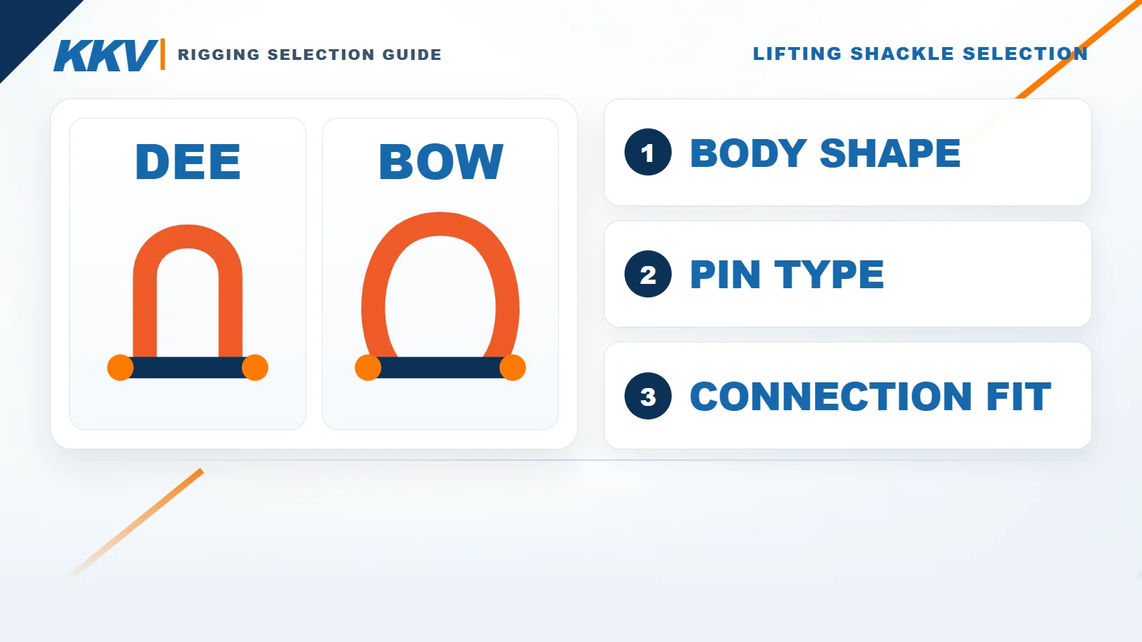
How to Choose a Lifting Shackle: Dee vs Bow, Pin Types, WLL and Connection Fit
Choosing a lifting shackle is not simply a matter of matching a stamped tonnage to the load weight. The shackle has to suit the complete load path: the body shape, pin-retention system, direction of force, sling arrangement, bearing surfaces, connection dimensions, working environment and applicable documentation must all work together. A shackle with enough nominal capacity can still be the wrong choice if the sling eye is pinched, the pad eye bears incorrectly, the pin can rotate loose or the load pulls the body out of line.
This guide explains how to choose a lifting shackle without turning one manufacturer’s data into a universal rule. It compares Dee and bow bodies, explains screw pins, safety bolts and round pins, and shows what information belongs in a technical enquiry. It does not publish a generic capacity or side-load chart because those limits depend on the exact manufacturer, product family and model.
Quick answer: Start with the maximum applied load and the complete connection arrangement, not the shackle’s nominal size. Choose a Dee or bow body according to the intended load path and the space required for the connected components. Then choose the pin-retention system for the duration, movement and vibration of the connection. Verify the marked WLL, load direction, any manufacturer-specific derating, pin diameter, bow clearance, bearing conditions, finish, temperature range, identification and certificates against the exact model data sheet. Treat the body, pin, nut and cotter pin as one matched assembly.
Table of contents
- Lifting shackle selection: the short answer
- What is a Dee (D) shackle?
- What is a bow (anchor) shackle?
- Dee vs bow shackle: side-by-side comparison
- Screw pin vs safety bolt vs round pin
- Calculate WLL from the complete applied load
- Check pin diameter, bow space and connection fit
- Side loading, sling angles and load control
- Environment, marking, certificates and traceability
- A seven-step shackle selection and RFQ process
- Pre-use inspection and common selection mistakes
- Frequently asked questions
Lifting Shackle Selection: The Short Answer
A shackle is a detachable connector used to join parts of a lifting or rigging system. Typical connections include a sling to a pad eye, a chain sling to a master link, a wire-rope eye to a lifting point, or a lifting accessory to another compatible component. The shackle is only one part of that system, so its WLL does not prove that the beam, lifting point, sling, hook, master link or attachment is suitable.
Use this sequence before selecting a catalogue number:
- Define the maximum load that can actually reach the shackle, including the effects of the number of sling legs, sling angle, centre of gravity and unequal load distribution.
- Draw the load path and decide whether the shackle will be loaded in line, at an angle, by one component or by an approved multi-leg arrangement.
- Choose the body geometry that allows the connected parts to seat without crowding, pinching or levering the shackle.
- Choose the pin type for a temporary, long-term, rotating, vibrating or dynamic connection.
- Measure the mating components instead of relying on their nominal names.
- Check the exact model’s WLL, permitted loading directions, reduction factors, temperature limits, finish and certification.
- Inspect the complete matched assembly before use and follow the lift plan and local requirements.
The terms Dee shackle, D shackle and chain shackle are often used for a relatively narrow body. The terms bow shackle and anchor shackle are commonly used for a wider, more rounded body. Terminology varies, so the drawing and dimensions are more reliable than the name alone.
The KKV D Shackle with Safety Bolt is a product example for compatible in-line rigging connections. Its page intentionally does not publish an unverified model-by-model WLL and dimension table. Request the exact size chart, pin details and certification for the supplied configuration instead of borrowing figures from another brand.
What Is a Dee (D) Shackle?
A Dee shackle has a comparatively narrow body whose sides are closer to parallel than the rounded sides of a bow shackle. That geometry can make it a compact connector for a single, aligned load path when the mating parts fit correctly. Manufacturer literature often describes standard Dee or chain shackles as mainly intended for one-leg systems, but that is a selection starting point rather than an absolute rule for every product carrying the name.
The narrow body offers less room for several sling eyes or links to spread across the bow. This is useful when the intended connection is one compatible component centred in the body, but it becomes a disadvantage if multiple components crowd one another, bear on the wrong area or force the shackle out of line. Do not force a wide sling eye, several sling legs or an oversized fitting into a Dee body simply because the stamped WLL appears adequate.
When considering a Dee shackle, confirm:
- the load will remain in the direction approved for that exact model;
- the connected item can seat centrally without bearing on the body eyes or threads;
- the pin passes through the mating hole with suitable clearance and bearing area;
- the body has enough internal width and length for the connection to articulate as intended;
- the pin-retention system suits movement, vibration and connection duration;
- the body and pin markings remain legible after installation;
- no component will apply an unapproved side load, twisting moment or prying action.
Some manufacturer-specific Dee shackles are approved for arrangements beyond a basic single-leg, in-line connection. That permission must come from the exact model instructions. Do not generalise it to another Dee shackle with a similar appearance.
What Is a Bow (Anchor) Shackle?
A bow shackle has a wider, more rounded body. The extra internal space can accommodate wider sling eyes or an approved arrangement of more than one sling leg without forcing them tightly together. For that reason, manufacturer guidance commonly describes bow or anchor shackles as mainly suitable for one-leg and multi-leg systems.
The wider shape does not automatically approve side loading. It also does not mean any number of sling legs may be placed anywhere in the shackle. In a typical approved two-leg arrangement, manufacturer instructions may require the sling eyes to bear in the bow while the pin connects to the hook or pad eye. The number of legs, included angle, symmetry and WLL basis must be checked for the exact product. Multiple sling legs should not be stacked on a pin unless the manufacturer explicitly approves that arrangement.
Choose a bow shackle when its geometry is needed for the connection, not because the word “bow” sounds stronger or more versatile. The product’s WLL and permitted load directions remain decisive. A compact Dee shackle may be the better fit for one aligned component; a bow body may be necessary when a wide synthetic sling eye needs adequate bearing width or when an approved bridle connection needs space in the body.

KKV currently does not publish a verified bow-shackle model page or model-specific table. If a bow or anchor shackle is required, include the body geometry and complete connection arrangement in the enquiry so the supplier can confirm a suitable product rather than substituting a visually similar connector.
Dee vs Bow Shackle: Side-by-Side Comparison
The table below is a decision aid, not a capacity table. Exact approval always comes from the selected manufacturer and model.
| Selection point | Dee (D) shackle | Bow (anchor) shackle |
|---|---|---|
| Typical body geometry | Narrower body with comparatively straighter sides | Wider, rounded body with more internal space |
| Common starting application | One compatible component in an aligned, often single-leg load path | Wider sling eyes or approved one- and multi-leg arrangements |
| Space for connected parts | More limited; crowding must be checked carefully | Greater, but components must still seat in approved locations |
| Multi-leg use | Do not assume it is allowed; check exact model instructions | Often selected for an approved bridle arrangement, subject to leg count, symmetry and angle limits |
| Side loading | Not approved merely because the body is forged; use exact instructions | Wider shape does not create automatic side-load approval; derating is model-specific |
| Main selection risk | Forcing a wide or multi-part connection into a narrow body | Treating the larger bow as permission for uncontrolled angular loading |
| Best quotation input | Load path, mating dimensions, pin type, WLL and required documents | The same information plus leg count, included angle and bearing arrangement |
Neither shape is automatically “better.” The correct body is the one whose verified rating and geometry suit the complete connection. If the load can shift, rotate or become asymmetric, resolve that behaviour in the lift plan rather than relying on the shackle body to correct it.
Screw Pin vs Safety Bolt vs Round Pin
The pin closes the shackle and transfers load through the mating component. It is part of the rated assembly, not a replaceable hardware-store fastener. The body, pin, nut and cotter pin are not interchangeable between different makes, sizes or models unless the manufacturer provides written approval. Do not replace the pin with an ordinary bolt, threaded rod or a pin taken from another shackle.
Screw-pin shackles
A screw pin threads directly into one shackle eye. Manufacturer guidance commonly positions it for temporary connections and pick-and-place work because it can be installed and removed quickly. The pin must be fully engaged and tightened in the specified manner before each lift. A live rope or moving connection must not be allowed to rotate the pin loose.
Secondary retention, sometimes called mousing, may be described by a manufacturer for particular circumstances, but it does not convert every screw-pin shackle into the preferred choice for a long-term or high-vibration installation. Where rotation, vibration or extended service can affect pin security, a safety-bolt configuration is normally a more appropriate starting point.
Safety-bolt or bolt-type shackles
A bolt-type shackle uses a bolt, nut and cotter or split pin. This arrangement is commonly selected for long-term or permanent connections and for cases where movement could loosen a screw pin. Every retention part specified by the manufacturer must be installed. The cotter pin is not decorative, and a nut alone is not the complete assembly.
The KKV D Shackle with Safety Bolt illustrates this retention concept. Confirm that the actual supplied shackle includes the correct matched bolt, nut and cotter pin and that the connection has enough clearance for installation and inspection.
Round-pin shackles
A round pin is retained by a cotter pin rather than by a threaded eye or nut. Some manufacturer guidance limits this type to strictly in-line loading and prohibits side loading or use as a collector for multiple legs. Because permitted uses vary, a round-pin shackle should only be selected from its own technical instructions, not by analogy with a screw-pin or safety-bolt product.
| Pin system | Typical selection starting point | What must be verified | Common mistake to avoid |
|---|---|---|---|
| Screw pin | Temporary connections and repeated pick-and-place work | Full thread engagement, tightening method, resistance to rotation and any approved secondary retention | Leaving the pin partly engaged or allowing a moving sling to unscrew it |
| Safety bolt / bolt type | Long-term, permanent, vibrating or movement-prone connections | Correct matched bolt, nut and cotter pin; installation clearance; inspection access | Omitting the cotter pin or substituting an unrelated bolt |
| Round pin | Limited applications defined by the manufacturer | In-line-only restrictions, correct cotter pin and prohibited side or multi-leg loading | Treating it as equivalent to a screw pin or safety bolt |
The pin choice should be made together with the body shape. “Bow shackle” does not identify its pin type, and “safety bolt” does not identify whether the body is Dee or bow.
Calculate WLL from the Complete Applied Load
Working Load Limit is the maximum load permitted by the manufacturer under defined conditions. It is not the minimum breaking load and is not a promise that the whole rigging system can lift the same value. The shackle must have a legible manufacturer marking and must not be loaded beyond the WLL applicable to the actual configuration.
Start with the maximum load that may reach the shackle. Include the lifted item, lifting attachments and any other weight transferred through that connection. Then evaluate how the load is distributed. In a multi-leg sling, the load on one leg is not simply the total weight divided by the number of legs. Sling angle, centre-of-gravity position, unequal leg length, stiffness and tolerances can make one leg carry more than the others.
Check these questions:
- Is the shackle at the top of a bridle, at a lower connection or in a single vertical leg?
- How many legs can carry load under the planned geometry?
- What sling angle is used in the manufacturer’s rated-capacity method?
- Can the centre of gravity shift during pick-up, travel or landing?
- Is the load dynamic, likely to snag or subject to shock?
- Will the shackle remain in line, or does the arrangement introduce side loading?
- Does the manufacturer require a lower WLL for the actual load direction or connection?
Never increase capacity by assuming that two shackles will always share a load equally. Never use the breaking load divided by a guessed safety factor to create a WLL. Use the marked rating and the exact manufacturer’s rated-load table for the selected product. If the marking is missing or illegible, do not estimate capacity from body diameter, colour or appearance.
The KKV Grade 80 Chain range and Chain Rigging pages can help define the surrounding sling assembly. Chain data is not shackle data: a chain diameter or chain-sling WLL does not prove that a particular shackle fits or has the required rating.

Check Pin Diameter, Bow Space and Connection Fit
Nominal size is not enough to prove compatibility. Two products described by the same tonnage can have different pin diameters, inside widths, body diameters and clearances. Obtain drawings for the shackle and every mating component, then check the contact conditions at the loaded position.
Pin-to-hole fit
The pin must pass through the pad eye, lug, lifting point or compatible fitting without being forced. The hole should provide the bearing and articulation conditions required by the exact model instructions. A hole that is too small prevents installation; a hole that is too large can create concentrated bearing, impact or an unsuitable bending condition. Check whether the threaded portion could enter the loaded bearing zone and whether the nut, collar and cotter pin remain accessible.
Body-to-sling fit
When a synthetic sling eye bears in a shackle bow, the bearing surface must be wide and smooth enough to avoid excessive folding, bunching or edge pressure. The sling should not be crushed between other components. Confirm the relationship between shackle curvature and sling-eye geometry with the sling and shackle manufacturers. A web sling or round sling WLL does not approve every connector diameter.
For product-specific sling details, see the EA Polyester Round Sling and EB Flat Webbing Sling pages. Use the existing EB URL even though its slug contains “falt”; changing an internal link to an assumed corrected slug would create a broken link.
Hook, link and chain fit
A hook or master link must seat on an intended load-bearing surface without being point-loaded against a sharp edge. The shackle should not jam in a hook bowl, press against a latch or prevent the hook from aligning with the force. The latch on an Eye Sling Hook with Latch retains loose rigging during slack conditions; it is not a load-bearing component and must not be used to carry the shackle.

Space for movement and inspection
Check the connection in every planned position, not only while it is unloaded on a bench. There must be enough space for articulation without the body contacting surrounding steel, enough room to install the pin-retention parts, and enough access to inspect markings and condition. If spacers are needed to centre a connection, use only an arrangement permitted by the shackle manufacturer. Do not weld washers to the shackle or bend the body to make it narrower.
Side Loading, Sling Angles and Load Control
An in-line shackle load follows the manufacturer-approved centreline, remains within the body plane and acts perpendicular to the pin axis, with the load centred as intended. Angular loading can include a force that departs from that centreline while still remaining within the body plane. Out-of-plane loading applies force across the shackle or pin axis and may be prohibited or subject to different restrictions. Manufacturer terminology varies, so identify the actual direction and angle on a drawing instead of relying on the words “side load” alone. Any departure from the approved in-line path can reduce permissible capacity, and some shackle types or product families prohibit it completely.
Do not copy a side-load reduction table from one manufacturer into a specification for another brand. Crosby, for example, publishes angular-loading reductions for defined Crosby screw-pin and bolt-type ranges, while Green Pin uses product-family instructions and curves with exceptions for particular designs. Those are manufacturer-specific rules, not universal percentages and not a substitute for the selected product’s data sheet.
For a bridle arrangement, verify:
- whether the exact shackle permits more than one sling leg;
- where the sling legs must bear—in the bow or on another approved surface;
- whether the pin connects to the hook, pad eye or lifting point;
- the maximum permitted number of legs and included angle;
- whether the load must be symmetric for the stated WLL;
- the required reduction for any departure from in-line loading;
- whether the load can move and change the angle during the lift.
Never side load a round-pin shackle unless its exact manufacturer instructions expressly allow the configuration. Do not allow several components to pile on one side of the bow. Do not use a shackle body as a lever to force holes into alignment. If the load path cannot remain controlled, redesign the rigging arrangement or obtain an engineered solution.
Shock loading is also different from a controlled static lift. Snagging, sudden acceleration, uncontrolled landing or taking up slack abruptly can create forces above the calculated suspended weight. The lift plan should prevent these events rather than adding an informal capacity margin to the selected shackle.
Environment, Marking, Certificates and Traceability
The same shackle may not be suitable for every temperature, chemical exposure, marine environment or regulated project. Finish and colour do not identify capacity or prove corrosion resistance. Ask the supplier to confirm the material, finish, temperature range and environmental restrictions for the exact model.
At minimum, review:
- manufacturer and product identification;
- legible WLL marking and the rating standard used;
- body and pin traceability marks;
- material and heat-treatment information where required;
- finish or coating and any effect on inspection;
- approved temperature range and any derating;
- required declaration, test certificate or material certificate;
- applicable standard and edition for the project jurisdiction;
- special requirements for offshore, subsea, hazardous or corrosive service.
In the United States construction context, OSHA 1926.251 requires rigging equipment to be inspected before use each shift and as necessary during use, requires defective equipment to be removed from service, and prohibits using shackles above the capacity shown by permanent, legible manufacturer identification. Other jurisdictions may impose different or additional requirements.
ASME B30.26 covers the construction, installation, operation, inspection and maintenance of detachable rigging hardware including shackles. Follow the edition applicable to the project, together with local law, the lift plan and the manufacturer’s instructions. Do not label a manufacturer reduction table as an ASME table unless the standard itself supports that statement.
Certificates should identify the supplied item, not merely a generic product family. Check that the shackle body and pin markings correspond to the documentation and purchase order. If traceability is a project requirement, define it in the RFQ before ordering.
A Seven-Step Shackle Selection and RFQ Process
Use the following process to turn a lifting task into a quotation that a supplier can evaluate.
Step 1: Describe the lifting task
State what is being lifted, maximum gross load, centre of gravity, lift orientation, travel path, lifting frequency and whether the load may rotate or shift. Identify the responsible lift plan or engineering drawing where applicable.
Step 2: Draw the complete load path
Show the lifting machine, hook, master link, sling legs, shackles, lifting points and load. Mark which component bears on the pin and which bears in the body. A simple annotated sketch often prevents a wrong selection more effectively than a tonnage-only enquiry.
Step 3: Calculate the maximum applied load
Calculate the highest force that can reach each shackle using the project-approved method. Include sling angles, leg distribution, centre-of-gravity offset and dynamic effects required by the governing procedure. Do not assume equal sharing without justification.
Step 4: Select body geometry and pin system
Choose a Dee or bow shape based on the connection space and approved load path. Choose screw pin, safety bolt or another manufacturer-approved system based on duration, rotation, vibration and removal frequency. Record why each choice suits the application.
Step 5: Measure every mating component
Provide pin-hole diameter and thickness, sling-eye width and thickness, hook or link dimensions, available inside clearance and any nearby obstruction. Confirm the connection in its loaded and articulated positions.
Step 6: Define environment and documents
State temperature, corrosion exposure, indoor or outdoor service, chemical contact and any offshore or special environment. List the required standard, declaration, inspection certificate, material certificate, proof-test evidence and traceability.
Step 7: Obtain written model confirmation
Ask the supplier to identify the exact model, WLL, dimensions, permitted load direction, pin-retention parts, reduction rules and certificates. Compare the supplied item against the approved quotation and drawing before first use.
| RFQ field | Information to provide | Supplier confirmation required |
|---|---|---|
| Maximum applied load | Calculated load at this shackle and calculation basis | Exact model WLL for the stated configuration |
| Load direction | In-line, angular, possible movement and side-load angle if applicable | Permitted directions and manufacturer-specific reduction |
| Body geometry | Dee or bow preference and reason | Product geometry suitable for the connection |
| Pin system | Temporary, long-term, rotating or vibrating service | Screw pin, safety bolt or other approved matched assembly |
| Mating dimensions | Hole, lug, sling eye, hook/link and clearance dimensions | Pin diameter, inside width/length and bearing compatibility |
| Environment | Temperature, corrosion, chemicals, offshore or indoor service | Material, finish, temperature limits and restrictions |
| Documents | Applicable standard, declaration and certificate requirements | Documents supplied with traceable item identification |
| Quantity and destination | Required quantity, delivery location and schedule | Availability, lead time, packing and shipping terms |
Pre-Use Inspection and Common Selection Mistakes
Selection is not complete when the purchase order is issued. Verify the received shackle against the approved specification, then inspect it before use according to the manufacturer, applicable standard and workplace procedure.
Check that:
- manufacturer, WLL and traceability markings are present and legible;
- the body and pin are the correct matched type, size and manufacturer;
- the body is not bent, twisted, stretched or otherwise distorted;
- the pin and body threads are complete and undamaged;
- the bolt, nut and cotter pin are all present where required;
- there are no cracks, severe nicks, gouges, heat damage or unacceptable corrosion;
- wear remains within the exact model’s removal criteria;
- the pin seats and retains correctly without force or improvised packing;
- the connection aligns and bears as shown in the approved lift plan;
- no unauthorised welding, grinding, heating, reshaping or repair is present.
Common mistakes include selecting only by stamped tonnage, assuming a wider bow permits any side load, using a screw pin in a connection that can rotate it loose, stacking several sling eyes on the pin, forcing an oversized fitting into a narrow body, allowing a sling to bear on threads, substituting a pin and copying another brand’s derating chart.
Another frequent mistake is treating inspection limits as universal. A manufacturer may publish a particular wear percentage or inspection interval for its products, but that figure must not be transferred automatically to an unidentified shackle. Use the exact instructions and local regulatory requirements.
If the pin will not engage normally, do not hammer it into place. If the connection needs welded spacers, bent side plates or improvised retention, stop and correct the design. If markings cannot be read or the body and pin cannot be positively identified as a matched assembly, quarantine the shackle until a competent person determines its status.
For additional manufacturer guidance, review the Crosby shackle application information and the Green Pin Shackles Pocket Pilot. These documents explain their own products; their numerical limits are not interchangeable with unverified shackles.
Frequently Asked Questions
Is a Dee shackle stronger than a bow shackle?
Body shape alone does not determine which shackle is stronger. Compare the marked WLL, exact product data and approved load configuration. A Dee body is often selected for a compact aligned connection, while a bow body offers more space for a wider or approved multi-leg arrangement. Two visually similar shackles can have different ratings and restrictions.
Can I use a bow shackle for side loading?
Not automatically. A wider bow does not by itself approve side loading. Check whether the exact product allows the planned angle and apply only the manufacturer-specific reduction for that model. Some product families are restricted to in-line loading.
When should I choose a safety-bolt shackle instead of a screw-pin shackle?
A safety-bolt or bolt-type shackle is a strong starting choice for long-term or permanent connections and where movement or vibration could loosen a screw pin. Use the specified nut and cotter pin. Screw pins are commonly used for temporary pick-and-place work, subject to full engagement, tightening and control against rotation.
Can I replace a lost shackle pin with a normal bolt?
No. The original body and approved pin form a rated assembly. An ordinary bolt may have the wrong material, diameter, thread, bearing length or retention system. Obtain the correct manufacturer-approved replacement or replace the complete shackle.
Should sling legs bear on the shackle pin or in the bow?
Follow the exact arrangement shown by the manufacturer and lift plan. In many multi-leg connections, sling eyes are required to bear in the bow while the pin connects to a hook or lifting point. Multiple legs should not be placed on the pin without explicit approval.
How do I know whether a synthetic sling eye fits a shackle?
Compare the sling-eye dimensions and minimum bearing requirements with the shackle’s curved bearing surface and internal space. The eye must not be sharply folded, pinched or crowded. Confirm the connection with both manufacturers when the fit is not clearly covered by published data.
Can I calculate shackle WLL from its body diameter?
No. Body diameter is not a reliable capacity identifier. Material, manufacture, heat treatment, pin design and product standard all affect rating. Use permanent legible manufacturer markings and the exact model documentation.
What information should be stamped on a lifting shackle?
Required identification depends on the applicable standard and jurisdiction. Where OSHA 1926.251 applies, permanently affixed and legible identification must show the manufacturer-prescribed safe working load; that paragraph does not separately state that the manufacturer name itself must be marked. Product standards, manufacturer instructions or project rules may require additional manufacturer and traceability markings. Do not use an unidentifiable shackle merely because it looks undamaged.
How often should lifting shackles be inspected?
Inspect before use as required by the applicable workplace procedure and regulation; OSHA construction rules require inspection before each shift and as necessary during use. Periodic inspection frequency depends on the governing standard, manufacturer instructions, service severity and local law. Do not turn one manufacturer’s suggested interval into a universal rule.
What should I send KKV for a shackle quotation?
Send the maximum applied load, drawing of the connection, load direction, number of sling legs and angles, preferred body and pin type, mating dimensions, environment, required standards and certificates, quantity and destination. Photographs help explain an existing arrangement, but dimensions and the load calculation are still required.
Specify the Complete Connection, Not Just the Tonnage
The safest and most efficient quotation starts with the application. A statement such as “two-ton shackle required” leaves unanswered questions about load distribution, body shape, pin security, connection dimensions, angular loading, finish and documents. A short load-path sketch plus measured dimensions allows the supplier to identify the information that must be confirmed before production.
KKV can review a Dee-shackle enquiry together with the surrounding chain rigging, Grade 80 chain and eye hook requirements. Model selection remains subject to written confirmation of the exact supplied configuration.
For shackle selection support, email sales@kkvhoist.com or contact KKV with your load-path sketch, maximum applied load, connection dimensions, operating environment, required documents, quantity and destination.
Safety note: This article is general product-selection guidance, not a lift plan, engineering calculation or substitute for the manufacturer’s instructions. A competent person must approve the complete rigging arrangement under the applicable law, standard and site procedure. Never exceed the marked WLL, shock load a shackle, use an unidentifiable or damaged assembly, or permit people beneath a suspended load.