Low Headroom Hoist vs Standard Hoist: Headroom, Hook Travel, Trolley Design and How to Choose
A low headroom hoist vs standard hoist comparison is mainly a study of geometry. Both configurations may have the required rated capacity, lift speed and lifting medium, yet place the upper hook position at very different heights. The correct choice depends on the distance from the runway or suspension point to the load hook, the travel path of the load, the beam and trolley arrangement, and the space needed for power, controls, maintenance and safe operation.
This guide focuses on electric chain hoists installed on or beneath a beam. It does not repeat the full capacity, duty-cycle, speed and power-supply selection process covered in How to Choose an Electric Hoist. Instead, it explains how to measure the available space, compare standard and low-headroom arrangements on a like-for-like basis, and send the dimensions a supplier needs to confirm a configuration.
The terms used by manufacturers are not perfectly uniform. “Standard headroom,” “normal headroom,” “regular trolley,” “low headroom” and “ultra-low headroom” can describe different constructions. Never purchase from the label alone. Compare the dimensioned drawing, exact capacity, chain fall, lift, beam range and trolley arrangement of the quoted model.
Quick answer: Choose a low-headroom hoist when a standard hook-suspended or conventional trolley-mounted hoist cannot raise the load high enough within the verified building and runway envelope. Measure from the relevant beam or suspension datum to the hook saddle at its highest permitted position, then calculate the highest achievable load-top elevation using the complete rigging stack and the signed offset between the load lifting point and the load top. Compare exact supplier drawings for the same capacity, lift, trolley type, power supply and duty. Also verify beam-flange fit, wheel geometry, side clearances, end approach, chain-container clearance, control and cable routing, maintenance access and structural suitability. Low headroom is not automatically better: if a standard arrangement provides the required hook position and clearance, it may be simpler to install, inspect, maintain or relocate.
Table of contents
- Define headroom before comparing hoists
- Survey the building, runway and load
- Understand a standard hoist layout
- Understand a low-headroom hoist layout
- Separate headroom, hook travel and useful lift
- Compare suspension and trolley designs
- Confirm beam, runway and travel compatibility
- Protect the full operating and service envelope
- Keep capacity, duty, speed and environment in the decision
- Choose by application, not by the smallest dimension
- Use the KKV HHSY configurations as a starting point
- Prepare a dimension-led RFQ
- Avoid common low-headroom selection mistakes
- Plan installation, commissioning and inspection
- Frequently asked questions
1. Define Headroom Before Comparing Hoists
For selection work, headroom is the vertical distance consumed by the hoist arrangement between a defined upper datum and the load hook when the hook is at its highest permitted operating position. The upper datum must be stated. It may be the bottom of a runway beam, the running surface of a trolley wheel, the centreline of a suspension pin, or another point shown on the manufacturer’s drawing. A number called “headroom” is not useful unless both measurement points are clear.
Use the hook saddle, not the tip of the hook or the bottom of a latch, as the lower reference unless the supplier drawing specifies another datum. The saddle is where the load attachment is intended to bear. If the application uses a lifting beam, shackle, sling or other below-the-hook device, that equipment does not normally change the hoist’s published headroom, but it does increase the complete rigging stack and lowers the highest possible position of the load.
“Low headroom” usually means that the hoist and trolley have been arranged to reduce the vertical distance between the supporting beam and the lower hook. A common method places the hoist body beside the beam rather than entirely below it. That geometry may improve the upper hook position, but it can increase the lateral envelope or change wheel, balancing, maintenance and chain-storage arrangements.
Likewise, “minimum headroom” on a brochure may apply only to one capacity, lift, chain fall, trolley and flange range. As capacity rises, a larger body, more chain falls, a deeper lower block or another trolley design may change the dimension. Request a project-specific drawing rather than scaling from a photograph.
2. Survey the Building, Runway and Load
Begin at the site, not in a catalogue. Record the space the hoist must occupy, the height the load must reach and the restrictions along the entire travel route. A measurement taken at one convenient point can miss a lower roof member, sloping beam, pipe, light fitting, cable tray, doorway, machine guard or runway splice.
Identify the highest required position of the load. For an assembly task, this may be the height needed to clear a machine, fixture or vessel rim. For maintenance, it may be the position needed to remove a motor or mold. Add the load’s own height and the actual rigging stack above it. The distance from the load’s lifting point to its top surface can be just as important as hoist headroom.
Establish a consistent site datum and measure the clear vertical distance to the floor or work surface. Then record beam depth, flange width, flange thickness, any flange taper, runway level, end stops, joints, curves and obstructions. Confirm dimensions at multiple travel positions. Existing drawings are useful, but they should be checked against the installed structure because later services or modifications may have changed the usable envelope.
The following worksheet separates the dimensions instead of hiding them inside one “available height” figure.
| Survey item | How to record it | Why it affects the decision |
|---|---|---|
| Upper structural datum | State the exact point and elevation used for every vertical measurement | Allows the supplier’s drawing to be compared with the site on the same basis |
| Beam section | Beam designation plus measured depth, flange width, flange thickness and flange shape | Controls trolley fit, wheel selection, side-plate spacing and possible clearance |
| Lowest overhead obstruction | Measure its elevation and horizontal position along the runway | May control the hoist body’s top or side envelope rather than hook headroom alone |
| Highest required load position | Record load top, lifting-point and required clearance elevations | Defines whether the load can clear the obstacle or reach the work position |
| Load and rigging geometry | Load height, centre of gravity, pick-point height, sling, shackle and lifting-beam dimensions | Determines the real hook position needed above the load |
| Travel route | Note columns, bracing, end stops, curves, doors, machines and service lines | Confirms the complete moving envelope, not just one parking position |
| Floor and lower limit | Record lowest hook or load position and any pit or lower level | Establishes required hook travel and chain storage |
| Service access | Record safe access route, platform position and removable-component space | Prevents an installation that cannot be inspected or maintained safely |
Measure operating tolerances as well as nominal distances. A runway may deflect under load, a building may have uneven steelwork, and the suspended load can move. Clearance must account for the engineered system and expected movement; it should not depend on components passing an obstruction with no practical margin.
Structural capacity is a separate verification. A tape measure can show that a trolley fits physically, but it cannot confirm that the beam, connections, runway supports or building can carry the wheel loads and dynamic effects. Provide the required reactions and obtain approval from the responsible engineer or other authorized party.
3. Understand a Standard Hoist Layout
A standard arrangement often suspends the hoist from a fixed point or beneath a separate trolley. With a trolley, the load path commonly runs from the beam through trolley wheels and side plates to a suspension pin, lug or hook, then through the hoist frame, load chain and lower hook. Much of the hoist body remains below the beam.
This arrangement is not an inferior design. Where vertical clearance is adequate, it can offer a straightforward load path, familiar installation, good component visibility and easier removal or relocation. A separate trolley may also let the buyer choose push, geared or powered travel independently, subject to the approved combinations. The KKV guide to push trolley vs geared trolley explains the travel-method decision; it should be made alongside, not after, the headroom study.
A hook-suspended hoist attached to a trolley can be convenient where equipment moves between approved locations. However, each interface adds vertical distance. The trolley depth, suspension component, upper hook or lug, hoist body and lower block all contribute to the upper hook position. Do not estimate this stack by adding unrelated catalogue dimensions; obtain the complete assembled drawing.
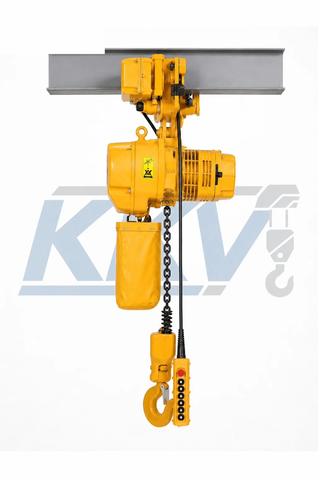
Standard arrangements are often appropriate for workshops with generous runway height, temporary lifting points, lower usage, or sites that value uncomplicated access more than the last increment of hook height. They may also be preferable when the low-headroom alternative would interfere with bracing, services or columns beside the beam.
4. Understand a Low-Headroom Hoist Layout
A low-headroom trolley arrangement typically integrates the hoist more closely with the trolley and positions substantial components beside the beam. The lower hook can then rise closer to the beam than it would beneath a conventional suspension stack. Exact construction varies by manufacturer, capacity and lifting medium.
The improvement must be read from a drawing for the exact ordered configuration. There is no responsible universal claim such as “saves 300 mm” or “provides 25 percent more lift.” A small-capacity single-fall chain hoist and a larger multi-fall model may differ considerably. A wider beam-flange range, longer lift, large chain container or powered trolley can also change the arrangement.
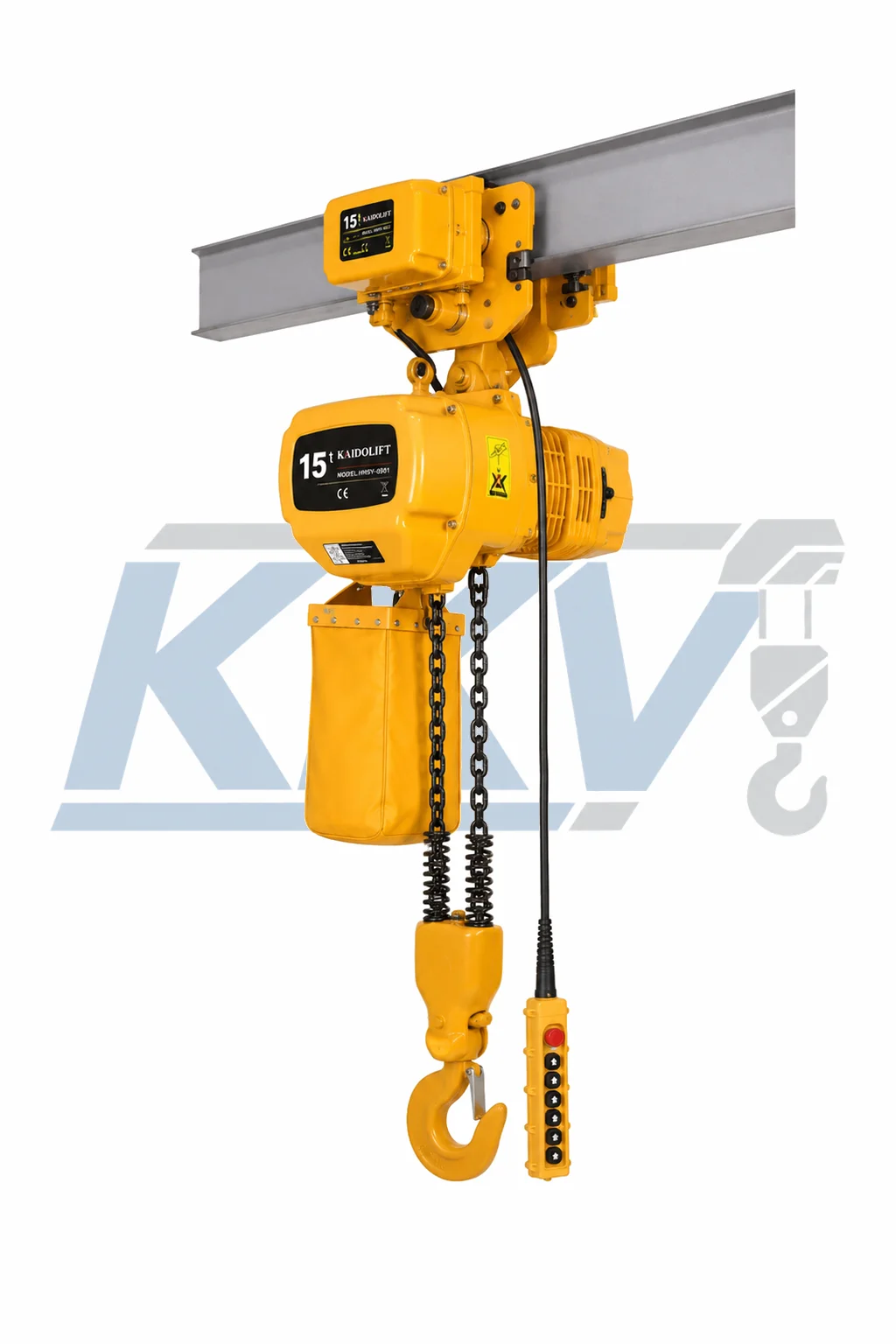
The compact vertical dimension creates other questions. Because the body may sit beside the beam, check its clearance to roof trusses, columns, runway brackets, conductor systems, festoons and adjacent equipment. Confirm whether the motor, gearbox, electrical enclosure and chain container remain within the allowed lateral and vertical envelope throughout travel.
Balance and wheel loading are engineered features of the trolley, not matters for field improvisation. Never offset, rehang, shorten, weld or add counterweights to a standard hoist in an attempt to make a low-headroom unit. Use only the manufacturer’s approved configuration and adjustment method.
5. Separate Headroom, Hook Travel and Useful Lift
Headroom describes the upper end of the geometry. Hook travel, often called lift, describes how far the hook can move between its permitted upper and lower positions. Useful lift is the portion of that travel that actually moves the load between the required pickup and set-down elevations after allowing for rigging and clearance.
A low-headroom hoist can improve the highest hook position without changing the ordered hook travel. Conversely, ordering a longer load chain can move the lower hook position farther down but does not automatically bring the upper hook closer to the beam. These are different requirements and should appear as separate lines in the RFQ.
Use a simple height stack for the highest load position:
- Start with the elevation of the upper structural or trolley datum.
- Subtract the quoted assembled headroom to locate the hook saddle at its highest permitted position.
- Subtract the vertical depth of the approved shackle, sling arrangement, lifting beam and other below-the-hook equipment under the planned load geometry.
- Apply the signed vertical offset from the load’s lifting point to its top surface: add the offset when the load top is above the lifting point, and subtract it only when the load top is below the lifting point. In elevation terms,
load-top elevation = lifting-point elevation + signed load-top offset. - Compare the resulting load-top elevation with the obstacle that must be cleared, including the engineering clearance required for movement.
Perform a second calculation for the lowest position. Confirm the hook can reach the pickup point without running to the lower limit or using the end anchorage as a working stop. The ordered lift must cover the required vertical movement plus the manufacturer’s operating margins; limit devices are not a substitute for correct chain length or operator control.
Rigging geometry can defeat an otherwise good hoist selection. A long master link, tall spreader, multiple shackles or shallow sling angles may consume more height than expected. Develop the hoist and rigging arrangement together, and include the weight of every below-the-hook item in the total suspended load.
6. Compare Suspension and Trolley Designs
First decide whether the load must remain at one lifting point or travel along a beam. A fixed suspension can be compact and economical, but it provides no horizontal movement. If the load must travel, select an approved trolley-hoist combination and define how the operator will control it.
A push trolley can suit lighter, accessible travel; a geared trolley adds a hand-chain loop for deliberate movement; and a motorized trolley supports frequent, long or remote-controlled travel. For each option, check the operator position, travel effort or speed, braking and the space required by hand chains, controls and electrification. Never pull a pendant or electrical cable to move a trolley.
“Low headroom” does not identify the trolley drive. A low-headroom unit may be supplied with a manual or powered travel arrangement, depending on the product family. Quote and drawing must identify the exact option. Compare side-by-side drawings for fixed, conventional trolley and low-headroom versions at the same capacity and lift.
Also check end approach: the horizontal distance from a defined end-stop or obstruction to the hook centreline at the closest permitted trolley position. A compact vertical arrangement may still have a long end approach because of bumpers, motor position or trolley length. If the load must reach a machine near a wall, end approach may control the selection.
Curved beams require explicit approval. Minimum curve radius, flange width variation, wheel profile and articulation can differ by capacity and trolley. Never assume a trolley suitable for a straight beam can negotiate a curve because its wheels physically fit the flange.
7. Confirm Beam, Runway and Travel Compatibility
Provide the beam designation where known, but also provide measured flange width and thickness. Rolled sections, fabricated beams and tapered flanges can require different wheel or spacer arrangements. Paint buildup, splice plates, welds and wear can reduce available running clearance.
Trolley wheels must suit the flange profile and be adjusted by the approved spacer or setting procedure. Too little clearance can cause binding and flange contact; too much can reduce guidance or create derailment risk. The manufacturer may specify permissible clearance and symmetry requirements. Those values belong to the exact trolley, not to trolleys generally.
Inspect the planned path for runway joints, end stops, bumpers, bolts, brackets and changes in flange width. A trolley that fits at the loading bay may not pass a splice or repair plate farther along the beam. Check both sides because a low-headroom body’s lateral envelope may be asymmetric.
Confirm the runway is level and aligned within the project requirements and that end stops are compatible with the trolley bumpers. End stops are not routine positioning brakes. If precise end positioning is needed, design the approach, controls and stopping method accordingly.
The building or runway designer must verify capacity and connections using the reactions for the selected equipment and service. Consider hoist and trolley self-weight, rated load, dynamic effects, travel forces and any applicable load combinations. A lighter-looking low-headroom assembly is not evidence that the existing beam is adequate.
8. Protect the Full Operating and Service Envelope
The hook-to-beam dimension is only one slice through a moving machine. Create an envelope drawing that includes the hoist body, trolley plates, motors, gearboxes, electrical boxes, bumpers, pendant support, power collectors or festoons, load chain, lower block and chain container. Check that envelope at every critical point on the runway.
The unloaded chain and chain container need particular attention. Longer lift means more stored chain, which can require a larger container and more clearance. The container must hang and move as designed without resting on the load, snagging services, entering the operator’s workspace or being squeezed against an obstruction. Do not shorten, fold or replace it with an unapproved container to gain space.
Allow the load chain to hang in its intended line. Side pulling can force the chain against guides, twist the lower block, swing the load and impose forces outside the intended vertical load path. Position the beam or lifting point above the planned load line rather than relying on the compact trolley to correct misalignment.
Plan power routing before approving the trolley. Festoon loops, conductor bars, collectors, junction boxes and cable supports occupy real space and move relative to the hoist. Check the cable at both travel extremes and through any vertical transitions. A pendant cable must be supported by its strain-relief system, not by electrical conductors.
Maintenance space is part of the envelope. Confirm safe access to inspection points, chain and hook components, trolley adjustments, brake, electrical enclosure, fasteners and lubrication points. Allow room to remove covers and replace components. A hoist that fits only after a cover becomes inaccessible creates an avoidable service problem.
9. Keep Capacity, Duty, Speed and Environment in the Decision
Headroom can narrow the field, but it cannot override the rest of the application. Rated capacity must be at least the maximum total suspended load permitted by the selection method, including rigging and below-the-hook devices. Unknown load weight must be resolved rather than covered by an arbitrary guess.
Provide starts, operating time, load spectrum, average travel and shift pattern so the supplier can confirm duty. State hoist and trolley speeds, positioning needs, supply voltage, phase, frequency and control voltage. Also describe indoor or outdoor exposure, temperature, moisture, dust, salt, chemicals and washdown. Special hazards and personnel lifting require equipment and procedures specifically approved for the service; a standard or low-headroom label says nothing about environmental suitability.
Review the broader KKV electric hoist category if the application requirements extend beyond one chain-hoist family. Use the separate electric-hoist selection guide to document capacity, duty cycle, speed and power before returning to the geometry comparison.
10. Choose by Application, Not by the Smallest Dimension
Choose the simplest approved arrangement that achieves the required hook and load positions while fitting the full envelope. Low headroom is valuable when its geometric benefit solves a measured constraint. It should not be selected only because it appears more compact on a product card.
| Application condition | Configuration to investigate first | Questions that decide the result |
|---|---|---|
| Fixed workstation with enough overhead space | Fixed or standard suspended hoist | Is horizontal travel unnecessary, and is the suspension point approved for the complete load? |
| Straight beam with generous height and occasional travel | Standard hoist with an approved manual trolley | Does the complete assembly reach both hook elevations, and can the operator move it safely? |
| Low existing roof or shallow runway-to-work distance | Low-headroom trolley hoist | What is the exact assembled headroom at the required capacity, lift and flange range? |
| Machine maintenance near a wall or column | Compare low-headroom and standard drawings | Which arrangement meets both upper hook height and required end approach without side collision? |
| Long or frequent powered travel | Powered trolley configuration | Do travel speed, braking, controls, power routing and service class suit the task? |
| Curved runway | Only a trolley explicitly approved for the curve | What minimum radius, beam profile, capacity restriction and articulation does the manufacturer allow? |
| Long lift with limited overhead clearance | Low-headroom option plus chain-storage review | Does the required chain container remain clear through all travel positions? |
| Temporary or frequently relocated work | Standard portable arrangement may be preferable | Are the suspension, inspection and relocation procedures approved at every location? |
Use an application drawing with the load at its highest and lowest positions, including rigging, nearby equipment and the operator zone. If both layouts work, compare equipment, structural changes, electrification, access, commissioning, inspection and downtime rather than purchase price alone.
11. Use the KKV HHSY Configurations as a Starting Point
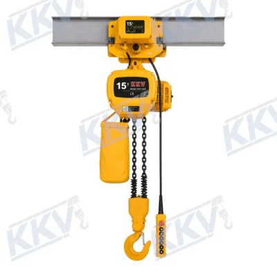
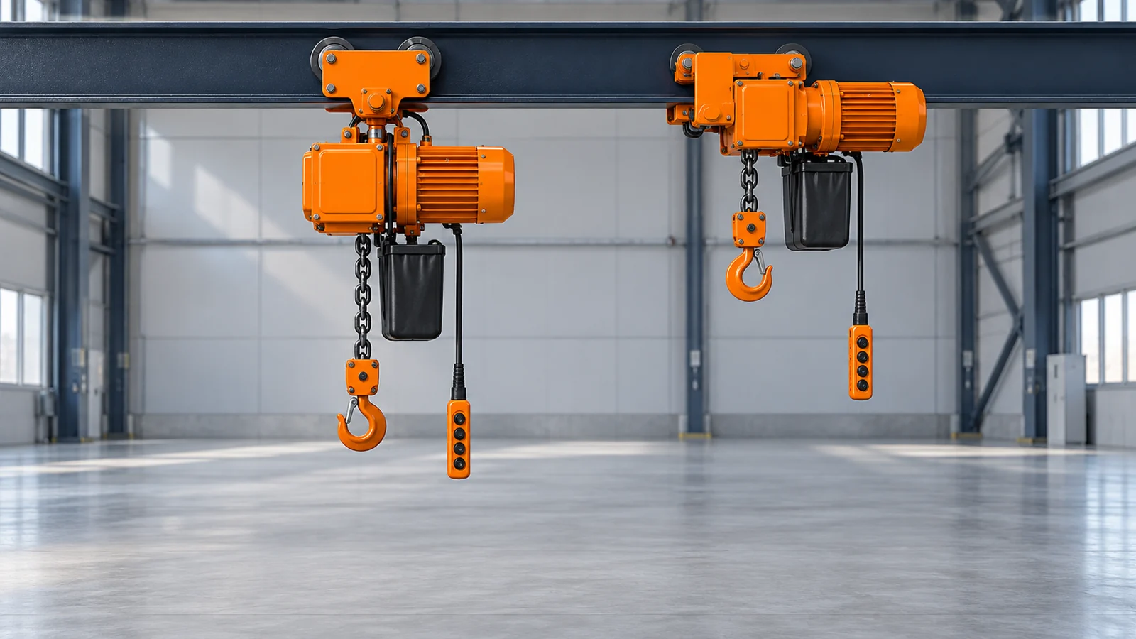
The KKV HHSY electric chain hoist is a useful starting point because the product family presents stationary, motorized-trolley and low-headroom arrangements. The listed range extends across multiple capacities, so the model name alone does not establish one headroom value or one beam range.
Use the page to identify the arrangement worth quoting, then request the exact technical schedule and dimensioned drawing. State capacity, lift, duty, speeds, electrical supply, flange dimensions, travel length and destination requirements. Ask KKV to mark the headroom datum, highest permitted hook-saddle position, overall body envelope, end approach and maintenance-clearance needs on the offered drawing.
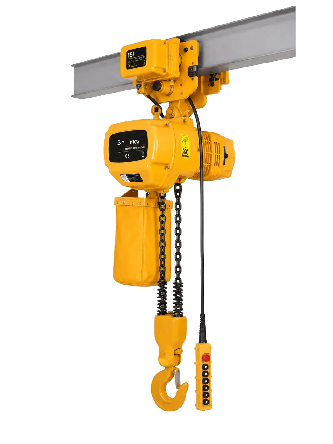
Do not infer the low-headroom model’s dimensions from the stationary or conventional motorized-trolley photograph. Confirm whether the offered unit is single speed or dual speed, which trolley drive is included, and which chain container corresponds to the ordered lift.
If the HHSY family does not match the application, compare alternatives in the KKV electric hoist range. Make the configuration drawing part of the quotation record, including capacity, lift, beam range, key dimensions, power data and project-specific limitations.
12. Prepare a Dimension-Led RFQ
A useful RFQ allows the supplier to reconstruct the installation. Send measurements with labeled photographs or a sketch, and distinguish verified values from estimates. If final structural dimensions are not available, request a preliminary selection subject to drawing approval rather than presenting assumed dimensions as fixed.
| RFQ field | Information to provide | Supplier confirmation to request |
|---|---|---|
| Load | Maximum total suspended load, typical load, centre of gravity and below-the-hook equipment | Rated capacity and any loading restrictions for the offered configuration |
| Required motion | Highest and lowest hook-saddle elevations, horizontal travel, end approach and positioning need | Headroom, hook travel, upper/lower limits, trolley length and closest hook centreline |
| Beam and structure | Section, flange width/thickness/shape, depth, runway length, curves, joints and approved capacity | Trolley adjustment range, wheel profile, clearances, reactions and permitted curve radius if applicable |
| Space envelope | Roof, columns, bracing, ducts, conductors, machinery and minimum required clearances | Dimensioned overall envelope on both sides and above/below the beam |
| Operating pattern | Starts per hour, operating time, load spectrum, shifts and travel frequency | Applicable duty classification and limitations |
| Speeds and controls | Hoist/travel speeds, single or dual speed, pendant or radio preference | Offered speeds, control method, emergency functions and stopping characteristics |
| Electrical supply | Voltage, phase, frequency, control voltage and supply route | Motor/control data, tolerances and electrification requirements |
| Environment | Indoor/outdoor, temperature, dust, moisture, chemicals, corrosion and special hazards | Suitability, enclosure/protection details and any required special version |
| Lift and chain storage | Required hook travel, floor/pit levels and clearance for stored chain | Load-chain length, falls, lower-block arrangement and chain-container size/location |
| Documents | Destination, language, required certificates, drawings and manuals | Exact document set, standards basis, inspection information and delivery revision |
If both arrangements could work, request standard and low-headroom drawings on the same capacity, usable lift, duty, speeds and environmental basis. Record responsibility for runway verification, trolley adjustment, electrification, installation, commissioning and any required testing before shipment.
Send the completed schedule through the KKV contact page and attach clear site dimensions. A short message such as “need 2-ton low headroom hoist” cannot establish beam fit or useful lift.
13. Avoid Common Low-Headroom Selection Mistakes
Comparing labels instead of drawings. “Low headroom” is not a standardized dimension. Compare marked datums and the exact assembled configuration at the required capacity.
Measuring from the wrong reference. A beam bottom, wheel running surface and suspension-pin centreline are different datums. State both endpoints of every dimension.
Ignoring the rigging stack. The hook may reach the calculated height while the top of the load remains below the required clearance because a spreader, sling and shackles consume space.
Treating longer chain as better headroom. More chain changes the lower reach and storage requirement; it does not automatically improve the upper hook position.
Assuming low vertical depth means a smaller total envelope. Side-mounted components can increase width and affect columns, bracing or adjacent runways.
Forgetting the chain container. Lift length affects stored chain. An undersized or obstructed container can disrupt chain feeding and create collision risks.
Field-modifying a standard trolley to gain height. Welding, drilling, offset suspension, unapproved spacers or improvised counterweights can change the engineered load path. Use a manufacturer-approved low-headroom configuration.
14. Plan Installation, Commissioning and Inspection
Begin with controlled access, a verified structure and the exact instructions. Confirm model, capacity, lift, trolley, chain container, power data and documents against the order. Set trolley spacing and retainers only by the approved procedure; verify wheel engagement, clearances, fasteners, end stops and bumpers. Install electrification so cables, collectors and festoons remain supported through the full route. Electrical work and internal adjustment require authorized personnel and isolation.
Commissioning scope depends on equipment, site and jurisdiction. It can include visual inspection, functional tests without load, direction checks, limits, brake response, trolley travel, chain feed, emergency functions and specified load testing. Use the manufacturer and applicable rules to define the test; do not improvise an overload.
After installation, measure the achieved highest and lowest hook positions and compare them with the approved drawing and application requirement. Traverse the hoist slowly through the complete route while observing all clearances. Verify the chain container and power system at both travel and hook extremes.
Establish pre-use, frequent and periodic inspection responsibilities. The program should cover the hoist, load chain, hooks, brake, controls, limits, trolley, beam, power system and support. Low-headroom geometry may make some components less visible, so plan safe access instead of accepting incomplete inspection.
15. Frequently Asked Questions
1. What is the difference between a low-headroom hoist and a standard hoist?
A standard hoist is often suspended below a fixed point or separate trolley, while a low-headroom arrangement integrates and positions components to bring the upper hook position closer to the supporting beam. The exact difference is the measured geometry on the two configuration drawings, not the product labels. A low-headroom design may use more space beside the beam.
2. How is electric hoist headroom measured?
It is measured vertically between the upper datum stated on the manufacturer’s drawing and the load-hook saddle at the highest permitted position. Because the upper datum varies by design, repeat both reference points whenever you quote a headroom number. Do not measure to the hook tip or assume the beam bottom is always the datum.
3. Does a low-headroom hoist provide more lifting height?
It can provide a higher upper hook position within the same building, which may increase useful vertical movement for the load. It does not automatically change the ordered hook travel. Calculate highest and lowest required hook positions separately and confirm both on the exact drawing.
4. How much headroom can a low-headroom hoist save?
There is no universal saving. The difference varies with capacity, chain falls, body and trolley design, flange range, lift and accessories. Compare dimensioned standard and low-headroom drawings prepared on the same selection basis. Avoid applying a percentage or millimetre value from another capacity or manufacturer.
5. Is a low-headroom hoist always the better choice?
No. If a standard arrangement reaches the required load position with adequate clearance, it may offer simpler installation, access, relocation or maintenance. A low-headroom body can have a larger lateral envelope or specialized trolley arrangement. Select it when its measured geometry solves the application without creating another conflict.
6. Does beam flange width affect hoist headroom?
It can. Flange width and thickness affect trolley adjustment, side-plate spacing and sometimes the offered configuration or key dimensions. Supply the actual beam section and measurements, including flange shape, and obtain the drawing for that setting. Never assume the narrowest-flange brochure dimension applies to every beam.
7. Can I convert a standard trolley hoist into a low-headroom hoist on site?
Not by rearranging or fabricating parts. The low-headroom arrangement is an engineered hoist-trolley system with defined load paths, balance, wheel loads and clearances. Use only a conversion or configuration expressly approved and documented by the manufacturer. Unauthorized welding, drilling, offset suspension or counterweights can be dangerous.
8. What measurements should I send for a low-headroom hoist quotation?
Send capacity, load and rigging geometry, highest and lowest hook positions, required travel, beam section and flange measurements, route obstructions, end approach, duty, speeds, power supply, environment and destination requirements. Labeled photographs and a dimensioned sketch help the supplier identify conflicting datums or missing clearances.
9. Does a longer lift require more space above the load?
Longer lift does not necessarily increase published hook-to-beam headroom, but it requires more load chain and therefore adequate chain-container capacity and clearance. The container’s size and position can affect the overall operating envelope. Confirm it for the ordered lift rather than relying on a standard photograph.
10. Where should I start when comparing KKV electric chain hoist configurations?
Start with the KKV HHSY electric chain hoist page, identify whether fixed, motorized-trolley or low-headroom travel matches the task, and then request capacity-specific drawings. For a wider shortlist, review the electric hoist category. Send the completed application data through KKV contact or email sales@kkvhoist.com.
Sources and Further Reading
- The Columbus McKinnon guide to factors in hoist selection discusses factors including capacity, lift, suspension and headroom. Use current manufacturer data for the offered model.
- The Hoist Manufacturers Institute Compendium of Basic Information and Standards for Hoists provides industry terminology and general selection, application, inspection and maintenance context.
- The ASME B30.16-2022 table of contents identifies the standard’s scope for overhead underhung and stationary hoists and its chapters on construction, inspection, testing and operation. Obtain the adopted full standard where applicable.
- OSHA 29 CFR 1926.554 states requirements for overhead hoists used in covered US construction work. Other workplaces and jurisdictions may have different or additional rules.
- The Harrington RHN electric wire rope hoist owner’s manual is an example of model-specific information for installation, dimensions, operation and maintenance; its values must not be transferred to another product.
- The KITO ER2 electric chain hoist technical document illustrates why capacity, suspension, trolley and dimensional data must be checked for the exact configuration rather than inferred from a generic hoist image.
Choose the Complete Hoist and Trolley Layout
The purpose of a headroom study is not to find the smallest published number. It is to prove that the selected hoist, trolley, beam, rigging and load can complete the required motion with safe clearances and service access. When the site survey and supplier drawing use the same datums, a standard-versus-low-headroom decision becomes measurable and reviewable.
For a configuration review or quotation, contact KKV and provide the dimension-led RFQ data, site photographs and beam information. KKV can then identify an appropriate starting configuration and confirm which project details still require engineering or local approval. You can also email sales@kkvhoist.com.
Safety note: This guide supports specification discussions; it is not an installation, structural-approval, commissioning or operating procedure. A qualified person must verify the support structure, beam, trolley fit, clearances, electrification and complete load path. Install, test, inspect and operate the delivered hoist in accordance with its exact manual and applicable law. Never lift people with equipment not designed and approved for that purpose, never stand beneath a suspended load, and never field-modify a hoist or trolley to gain headroom.