How to Choose a Permanent Magnetic Lifter: Capacity, Plate Thickness, Surface Condition and Safety
Learning how to choose a permanent magnetic lifter starts with the workpiece, not the largest capacity printed in a catalogue. A suitable lifter must be approved for the actual steel grade, verified load weight, plate thickness, contact area, surface condition, shape, orientation and operating environment. The crane or hoist, hook connection, support structure and procedures must also be suitable for the complete lift.
A permanent lifting magnet can handle compatible ferromagnetic steel without an external power supply, but magnetic attraction is sensitive to the circuit between the lifter and load. Thin material, coatings, rust, scale, dirt, curvature, roughness or incomplete contact can reduce performance. This guide supports quotation preparation; it does not replace the exact manual, model-specific load chart, lift plan or assessment by a competent person.
Quick answer: Confirm compatible ferromagnetic material, maximum weight and centre of gravity, then check the exact rated-capacity chart for thickness, shape, contact, surface and orientation. Select from rated capacity, not breakaway force. Verify full approved pole contact, correct positioning and workpiece stability. For long, flexible, curved, coated, rusty or uncertain loads, send drawings and material data instead of applying a generic reduction factor. Confirm the supporting hoist, connection, route, environment, inspection and operating procedure.
Table of contents
- Understand what a permanent magnetic lifter does
- Confirm the workpiece is magnetically compatible
- Establish the complete load weight and centre of gravity
- Separate rated capacity from maximum breakaway force
- Verify plate thickness and magnetic saturation
- Account for surface condition and air gap
- Match the lifter to flat, round and irregular workpieces
- Position the lifter and plan multiple-lifter arrangements
- Check lifting direction, motion and supporting equipment
- Assess temperature, environment and special hazards
- Compare magnetic lifters with plate clamps
- Use the KKV SY range as a selection starting point
- Follow a six-step selection and RFQ process
- Avoid common mistakes and plan safe use
- Frequently asked questions
1. Understand What a Permanent Magnetic Lifter Does
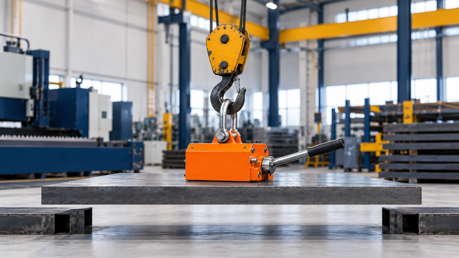
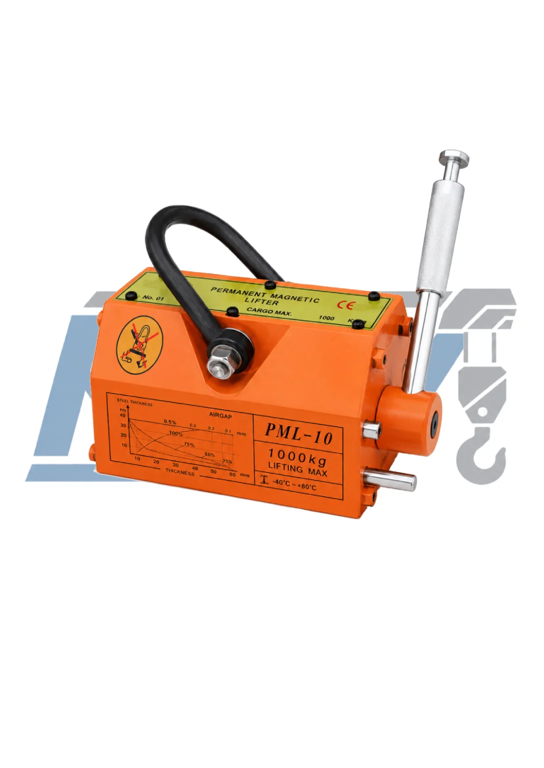
A manually operated permanent magnetic lifter contains a permanent-magnet system and pole faces that form a magnetic circuit through a compatible workpiece. Moving the control handle to the specified ON position changes the internal magnetic path so that flux passes through the load. Returning the handle to OFF releases the workpiece after it has been fully supported. The exact mechanism, locking arrangement and operating sequence belong to the individual model.
No continuous electrical supply is needed to maintain magnetic force, but the attachment is not fail-safe. Holding still depends on correct selection, approved engagement, component condition and disciplined operation. It is also only one element in the path from support structure to workpiece. Review the electric-hoist selection guide for the overhead equipment and the lifting-shackle selection guide if a connector is needed.
Start the application review by separating known facts from values that still need confirmation.
| Selection input | What to record | Why it matters |
|---|---|---|
| Workpiece | Material grade, heat treatment, dimensions, shape, weight and centre of gravity | Establishes whether a magnetic lift is feasible and where the attachment must act |
| Contact interface | Thickness beneath the poles, flatness, roughness, coatings, rust, scale, dirt, holes and edge distance | Determines whether the tested magnetic circuit can be achieved |
| Required movement | Initial orientation, final orientation, travel distance, acceleration, turning and set-down method | Reveals side loading, peeling, impact and stability risks |
| Lifting system | Hoist capacity, hook or connector fit, controls, support and available headroom | Confirms the complete load path rather than the magnet alone |
| Workplace | Temperature, moisture, dust, corrosives, restricted areas and people below | Determines environmental suitability and operational controls |
| Compliance | Destination, governing rules, inspection plan, certificates and language | Defines the documentation and approval basis for the supplied unit |
2. Confirm the Workpiece Is Magnetically Compatible
Permanent magnetic lifters are intended for materials that can conduct the required magnetic flux. Many carbon steels and some alloy steels are ferromagnetic, but a material’s commercial label or appearance is not enough to approve it. Chemical composition, microstructure, heat treatment and fabrication history can change magnetic response. Ask for the material specification and use the manufacturer’s permitted-material data for the exact lifter.
Do not assume that every steel behaves like the reference material used for a published rating. Many stainless-steel grades are weakly magnetic or effectively non-magnetic for this purpose, while some grades or cold-worked areas may show attraction without providing a verified lifting capacity. Aluminium, copper, brass, many other non-ferrous metals and non-metallic materials are not suitable loads for a conventional permanent steel lifting magnet. A magnet sticking to a sample is not a capacity test.
Cast, forged, heat-treated, hollow or fabricated parts may have section changes or internal geometry that interrupt the magnetic path. Where the grade differs from the rating basis, obtain model-specific approval. If material identity is uncertain, do not lift it magnetically until it is identified and reviewed.
The UK Health and Safety Executive’s guidance on magnetic lifting devices highlights the need to consider the load’s material, thickness, surface condition and shape. Treat these as selection inputs, not inspection details to be considered after purchase.
3. Establish the Complete Load Weight and Centre of Gravity
Use a verified mass from a drawing, scale, material certificate or controlled calculation. Include every item that the magnet will support. If the workpiece contains fixtures, retained scrap, attached components or trapped process material, their weight and effect on balance must be known. Do not select from a nominal plate description when thickness or dimensions vary.
Locate the centre of gravity in all relevant axes. The lifting force must act so the workpiece remains stable rather than rotating, tilting or peeling away from one pole edge. For a uniform rectangular plate, the geometric centre may be a useful starting estimate, but cut-outs, tapered sections, welded features and uneven attachments shift the actual centre. Marked lifting positions should come from an approved drawing or procedure.
The lifter, connector and any beam count against the crane or hoist capacity, even though they are not part of the workpiece carried by the magnetic interface. Keep those two calculations distinct.
Long plates deserve a stiffness check as well as a weight check. A thin sheet can sag, flutter or peel at an edge. The force distribution may cease to resemble the condition under which a single lifter was rated. A rigid lifting beam with multiple approved lifters may be appropriate, but its design, spacing and load sharing require manufacturer and engineering input.
4. Separate Rated Capacity from Maximum Breakaway Force
Rated capacity and breakaway force describe different things. Maximum breakaway force is not the working load limit. A breakaway value is obtained under defined test conditions; it is not permission to lift that force or ignore restrictions for thin, rough, curved or non-reference material.
Use the listed rated capacity; never use maximum breakaway force as WLL. The rated value must itself be checked against the exact manufacturer load chart and all application limitations. If a chart gives reduced capacities for material, thickness, air gap or round loads, use the permitted result for the combination of conditions rather than applying only one factor.
| Published term | What it can tell you | What it must not be used to claim |
|---|---|---|
| Rated lifting capacity | The manufacturer’s usable capacity under its stated reference conditions and restrictions | That every load below the number is acceptable regardless of thickness, material or contact |
| Working load limit, when used by the manufacturer | The maximum service load allowed within the stated configuration and conditions | That proof, test or breakaway values are additional usable capacity |
| Maximum breakaway force | A model-specific separation result under defined test conditions | A service WLL, an overload allowance or a universal safety factor |
| Proof or verification test load | Evidence from a specified test procedure | Permission to repeat the test in normal operations or exceed the rating |
| Reduced capacity from a load chart | The allowed value for the stated material, thickness, shape or air-gap condition | A generic percentage that can be transferred to another model or brand |
Published relationships between rated and breakaway figures can be useful for checking that a quotation matches its data sheet, but they are not universal design factors. On the current KKV SY product page, the listed maximum breakaway force is 3.0 times rated capacity from SY-100 through SY-1000, while it is 2.5 times rated capacity from SY-2000 through SY-5000. Those are model-specific published ratios. The test-piece conditions are not published on the page, so neither ratio should be called a universal safety factor or used to increase allowable load.
5. Verify Plate Thickness and Magnetic Saturation
The workpiece must provide enough ferromagnetic cross-section beneath and around the pole faces to carry the magnetic flux required by the rated condition. If the plate is too thin, it can become magnetically saturated: adding magnet strength cannot force proportionally more useful flux through the limited section. Effective lifting capacity can therefore be lower than the full rating even when the pole face is clean and the plate weight is modest.
Minimum acceptable thickness is not one universal millimetre value. It depends on the lifter’s magnetic circuit, pole geometry, capacity, reference material and the required load. A value from another brand, another capacity or an online chart cannot be transferred safely. Request the exact manufacturer load chart and identify whether its thickness refers to the local thickness directly under the whole pole area or to another defined dimension.
Layered sheets are a separate hazard: an extra sheet may follow unpredictably and later separate. Do not treat a stack as one solid plate unless the manufacturer and procedure expressly permit it.
Thin plates can also deflect. The centre may rise while edges remain on the support, creating a peeling action and rapidly changing the contact interface. Deflection can worsen as the plate leaves the support. The supplier needs length, width, thickness, material, pick-point position and planned acceleration to assess whether one lifter is suitable or a spread arrangement is required.
6. Account for Surface Condition and Air Gap
Magnetic performance depends on close contact between the pole faces and a suitable workpiece. Any non-magnetic separation creates an air gap in the magnetic circuit. Paint, mill scale, rust, oxide, plating, dirt, weld spatter, labels, protective film and surface waviness can act as gaps even when they appear thin. Rough machining marks or a bowed plate can concentrate contact on small high spots.
Do not assume that compressing a coating restores the rated condition. Define the supplied surface and obtain the permissible capacity or preparation method; grinding may damage the workpiece or its protection.
Inspect the lifter’s pole faces as well as the load. Nicks, embedded debris, corrosion, wear or distortion can prevent full contact. Repairs must not change pole geometry or create an unapproved shim. Never place cardboard, cloth, timber, rubber or packing between the lifter and load to protect the finish unless a model-specific engineered method explicitly allows it.
The procedure should define acceptable contact, cleaning and rejection. Wet or oily workpieces affect both magnetic contact and sliding risk. A preliminary lift does not make an unverified surface rated.
The Industrial Magnetics FX lifting-magnet manual and the Eriez lifting-magnet installation, operation and maintenance manual illustrate why selection and operation must follow the exact manufacturer’s tables and instructions. Their model-specific values are useful only for the equipment they cover and must not be copied into a KKV selection.
7. Match the Lifter to Flat, Round and Irregular Workpieces
A lifter rated on a flat reference plate does not automatically have the same capacity on round bar, pipe or a curved casting. Flat pole faces may touch a round workpiece only along narrow lines. The smaller effective contact area and altered magnetic path can reduce holding performance, while an unstable part may roll under the device.
Some permanent lifters have a pole profile and a separate capacity chart for approved round loads. Use that chart only when the exact diameter, material, wall or section condition and orientation are within its stated range. Do not assume that a V-shaped feature visible in a photograph establishes pipe capacity. Hollow pipe also provides a different magnetic section from solid round bar.
For irregular parts, map which pole areas touch, whether bosses or welds hold the body away, and whether the part can rotate after leaving its support. Grooves, holes, cavities and cast skins can defeat apparent contact.
Approval for a top lift does not automatically permit side-face pulling, plate rotation or holding during machining. Side forces can encourage sliding or peeling. Obtain written approval for the exact orientation and motion; otherwise use another lifting method.
8. Position the Lifter and Plan Multiple-Lifter Arrangements
Place a single lifter so its lifting line passes through or is appropriately aligned with the workpiece’s verified centre of gravity and its full pole area contacts approved material. An off-centre pick can tilt the workpiece, load one end of the pole face first and create a peeling action. It can also make the load swing as soon as it clears the support.
Keep the contact area away from edges, holes, slots, weld beads and abrupt thickness changes unless the manufacturer’s chart or application drawing accounts for them. There must be enough continuous material around the poles to complete the magnetic circuit. Marking an approved pick zone on repetitive workpieces can reduce setup variation.
Two or more lifters may be required for a long, flexible or wide load, but their capacities cannot simply be added. A plate and lifting beam are not perfectly rigid; tolerances, deflection and an offset centre of gravity can make one unit carry more than another. The beam, suspension points, spacing, equalization method and individual lifter capacities must be designed for the real load distribution and credible imbalance.
Provide the supplier with the full plate envelope, minimum and maximum thickness, stiffness information, centre-of-gravity range and proposed pick spacing. If a lifting beam is used, its self-weight and rated capacity must be included in the overhead-hoist calculation. The arrangement should be reviewed as one below-the-hook device, not as several independent catalogue items.
9. Check Lifting Direction, Motion and Supporting Equipment
Define the load’s complete journey: where it starts, how it clears the support, whether it travels horizontally, whether it turns, and how it is set down. Permanent magnetic lifting capacity is commonly presented for a direct lifting condition on a defined test piece. Acceleration, sudden stopping, collision, swinging, side pull and impact can produce forces and interface conditions that the static rating does not describe.
Align the hoist above the approved pick point before tensioning. Do not drag the lifter across the surface under load or use it to pull a plate sideways. Raise smoothly under the exact operating procedure and keep the travel path clear. The operator must be able to control the load without placing hands or feet under it.
The hook or shackle must seat correctly, articulate without binding, and avoid point loading or crowding. Select any connector by verified WLL, dimensions and direction; appearing on the same website does not prove compatibility.
The crane or hoist must support the workpiece, magnet, connector and beam. Confirm capacity, duty, speed, limits, brake, controls and structure. No generic speed makes an unsuitable interface safe.
Plan the exclusion zone and route before engagement. Keep personnel away from the fall zone and never lift over people. If travel would pass above occupied workstations, redesign the route or control access rather than relying on the magnet’s breakaway number.
10. Assess Temperature, Environment and Special Hazards
Magnets and internal components have temperature limits. Hot workpieces can reduce magnetic performance or permanently damage magnet material, while very low temperature can affect mechanisms, lubricants and the workpiece. Do not borrow a temperature limit from another product. Provide both the workpiece temperature and ambient range and obtain the approved limit for the exact model.
Water, coolant, oil, abrasive dust and corrosive chemicals can affect contact, handle operation, identification and inspection. Outdoor use introduces rain, ice and storage concerns. State whether the device will be exposed continuously or only during occasional lifts and ask about cleaning, corrosion protection and storage requirements.
Explosive atmospheres, cleanrooms, offshore sites and strong external magnetic fields need separate assessment. Magnets can affect pacemakers, magnetic media and sensors; establish controls from competent sources rather than inventing a general clearance.
Do not use a general-purpose permanent magnetic lifter to lift people, support an occupied platform or suspend a load for personnel to work beneath. Do not use it as a welding earth, clamp, positioning fixture or long-term support unless the manufacturer has designed and approved that duty.
11. Compare Magnetic Lifters with Plate Clamps
Magnetic lifters and plate clamps both handle steel, but they create different load paths and have different limitations. A magnetic lifter relies on a verified magnetic circuit through compatible material. A plate clamp uses a manufacturer-defined mechanical gripping action at an approved plate edge or surface. Neither is a universal substitute for the other.
A magnetic lifter may avoid placing a jaw on an edge and can be convenient when there is a clean, accessible top surface. A clamp may be considered where the material is unsuitable for magnetic lifting, the approved movement includes a vertical plate orientation, or the application matches a clamp’s exact design. Clamp selection introduces its own requirements for thickness range, surface hardness, minimum load, jaw condition, direction, number of clamps and sling geometry.
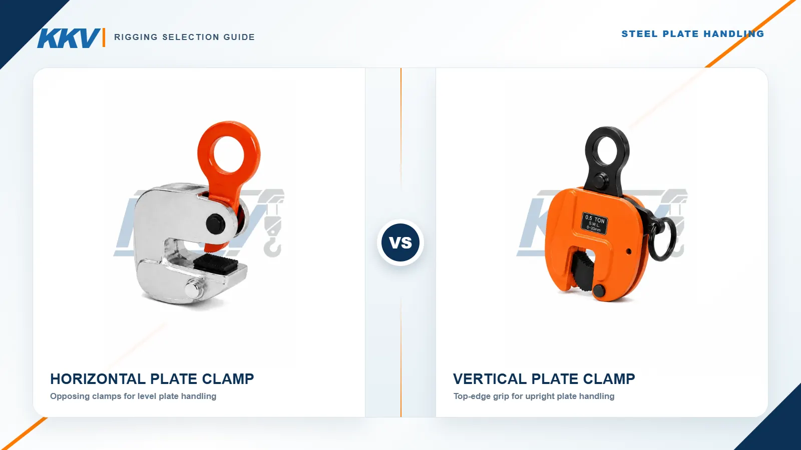
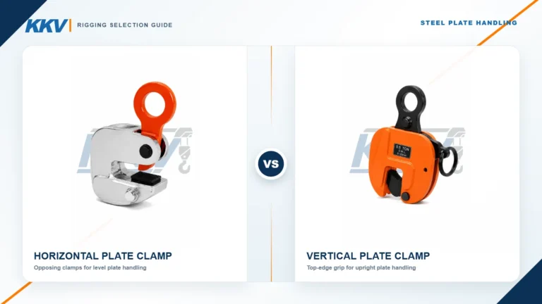
Use the KKV guide to horizontal vs vertical plate lifting clamps to understand the basic clamp distinction. Then compare the exact candidate magnet and clamp against the same workpiece data and lift plan. Do not choose solely on which device leaves fewer surface marks; both systems require a suitable interface and controlled use.
12. Use the KKV SY Range as a Selection Starting Point
The KKV SY permanent magnetic lifter product page lists eight models with rated capacities from 100 kg to 5,000 kg. Use that range to identify candidate models, not to approve an application from load weight alone. The page also lists dimensions, device weights and maximum breakaway-force values; the complete specification should be confirmed in the quotation and supplied manual.
Avoid copying the full eight-model table into an application worksheet without its conditions. Start with the workpiece weight, then provide material, thickness, flat or round shape, contact surface, dimensions and centre of gravity so KKV can identify the applicable model data. Ask for the exact manufacturer load chart and any restrictions for the intended workpiece.
As noted earlier, the published breakaway-to-rated relationship changes within the range: it is 3.0 for the listed SY-100 through SY-1000 models and 2.5 for the listed SY-2000 through SY-5000 models. These numbers describe the current page entries; they are not extra capacity, and they should not be treated as universal safety factors. Testing basis and workpiece conditions must be confirmed in the product documentation.
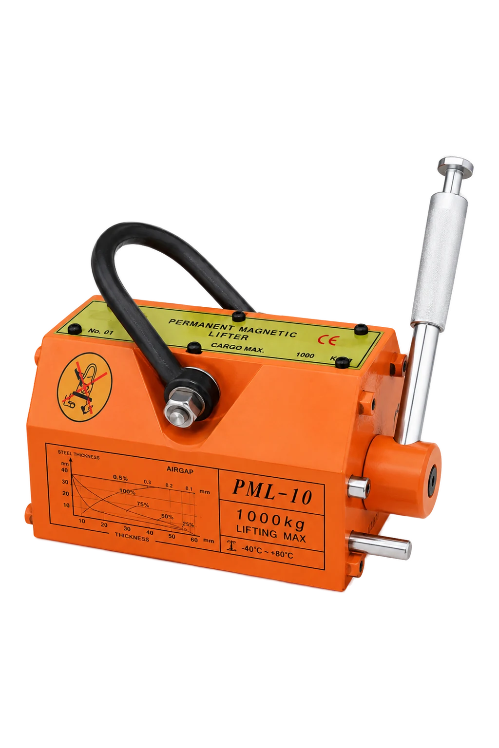
Product photographs do not establish scale, pole dimensions, handle clearance or hook fit. Request a dimensioned drawing. Confirm model identification as well; the current page writes SY400 without the hyphen used in most other model names.
Browse the wider KKV lifting equipment range for supporting equipment, but keep product selection and project approval separate. The final purchase record should identify capacity, exact model, applicable workpiece conditions, documents, destination and any approved special limits.
13. Follow a Six-Step Selection and RFQ Process
Step 1: Define the workpiece family. Record material, condition, maximum weight, dimensions, local thickness, shape and centre-of-gravity range. Separate flat, solid-round, hollow and irregular parts.
Step 2: Map the contact interface. Mark coatings, rust, scale, roughness, curvature, holes, grooves, welds and edge distance on photographs or a drawing. Define permitted preparation and the worst approved surface.
Step 3: Describe the lift. Show initial and final orientations, travel, turning, starts and stops, set-down support, obstructions and occupied areas. State whether stacked sheets are nearby.
Step 4: Define the supporting system. Provide crane or hoist capacity, hook and connector dimensions, headroom, controls and any lifting beam. Have the structure and overall system verified.
Step 5: Confirm the model-specific rating. Request the chart for material, thickness, flatness, air gap, shape and orientation. Ask for drawings, temperature limits, inspection criteria, test information and documents.
Step 6: Close the controls. Agree on marking, training, checks, examinations, maintenance, storage, exclusion zones and lift sequence. Ensure the manual and certificates match the delivered model.
Use the following RFQ schedule so the supplier can answer with a traceable selection rather than a generic catalogue link.
| RFQ field | Information to send | Confirmation to request |
|---|---|---|
| Workpiece identity | Drawing, part number, material grade, heat treatment and batch variation | Material compatibility and rating basis |
| Load data | Maximum weight, centre of gravity, dimensions and stiffness concerns | Applicable rated capacity and number of lifters |
| Contact face | Local thickness, flatness, roughness, coating, rust, scale, dirt, holes and grooves | Permitted surface condition, preparation and any model-specific reduction |
| Shape | Flat plate, block, solid round, pipe or irregular casting/fabrication | Approved geometry and load chart for that shape |
| Movement | Initial/final orientation, lift height, travel, acceleration, turning and set-down | Permitted lifting directions and operating restrictions |
| Lifting system | Hoist, hook or shackle dimensions, beam arrangement and available headroom | Interface fit, total suspended mass and drawing |
| Environment | Workpiece/ambient temperatures, indoor/outdoor exposure, water, oil, dust and chemicals | Temperature limits, protection, cleaning and storage requirements |
| Use pattern | Lifts per shift, part mix, operator position and stacking conditions | Suitability, procedures and any duty-related restrictions |
| Compliance | Country, governing rules, inspection scheme, document language and certificates | Standards basis, manual, declaration, test and traceability documents |
| Delivery record | Exact model, serial/ID method, accessories and spares | Final revision-controlled data matching the supplied unit |
Attach a workpiece drawing rather than relying on terms such as “clean steel.” Mark provisional data and require final approval before use. Retain the supplier response, drawing and limits.
14. Avoid Common Mistakes and Plan Safe Use
Selecting by load weight alone. A 500 kg workpiece does not automatically suit a 500 kg lifter. Material, thickness, surface, contact area, shape and motion can reduce or invalidate the rating. Resolve all of them before ordering.
Treating pull-off force as capacity. A large breakaway value is not permission to overload the device. Use the approved rated capacity for the actual workpiece conditions.
Using generic rules or judging by feel. Minimum thickness and permitted surface condition change with model. Obtain the exact chart; hand force and visual contact do not reproduce load, deflection or peeling.
Adding capacities in a multi-lifter system. Unequal load sharing, plate deflection and an offset centre of gravity can overload one device. Design the beam and arrangement as a system.
Switching OFF before support is complete. Set the workpiece on a stable, suitable support and remove magnetic load before release. Never use the handle to control a suspended or partly supported load.
Before use, confirm identification and capacity markings are legible; the lifting eye, body, handle, lock and pole faces are sound; and the workpiece matches the approved material, weight, thickness, shape and surface. Verify the pick, route, landing area and exclusion zone. Defects or uncertainty require removal from service.
Engage it only as the manual specifies and confirm handle locking before applying hoist tension. During any approved preliminary lift, keep the workpiece close to its support and people clear; this does not validate an unapproved load. Lift smoothly, avoid shock and side pull, and never leave the load unattended.
Set inspection, maintenance and testing from the instructions, law and service. Do not modify, open or remagnetize the device without manufacturer authorization and qualified work. Record return-to-service decisions.
Authoritative references for the responsible person:
- The UK HSE page on magnetic lifting devices summarizes application factors and safe-use concerns.
- The Industrial Magnetics FX manual provides a manufacturer example of model-specific selection and operating controls.
- The Eriez lifting-magnet manual provides another manufacturer-specific installation, operation, inspection and maintenance reference.
- The Columbus McKinnon TIGRIP TPM operating manual shows why capacities and permitted workpiece conditions must be taken from the exact device data.
- ASME B30.20 addresses below-the-hook lifting devices within its scope; obtain the applicable full edition and local adoption requirements.
- ISO 17096 addresses safety requirements for load lifting attachments and includes permanent lifting magnets within its scope; confirm applicability and obtain the complete standard where required.
These references do not create one combined set of capacities. Values and procedures from one manufacturer’s manual belong to its equipment. The delivered KKV model must be used with its own current documentation and the rules applicable at the destination.
15. Frequently Asked Questions
What rated capacity permanent magnetic lifter do I need?
Start with maximum verified weight, then check the exact rated-capacity data for material, thickness, contact, surface, shape and orientation. The permitted result for all combined conditions must cover the load. Also verify balance, rigidity and crane or hoist capacity; never substitute breakaway force.
Does a magnetic lifter’s rated capacity apply to thin steel plate?
Not automatically. Thin steel may not carry enough magnetic flux and may deflect or peel. Use the exact model’s thickness or capacity chart for the actual material and load. Send plate dimensions, weight and surface details; there is no universal minimum thickness.
What is the difference between rated lifting capacity and maximum breakaway force?
Rated capacity is the service value allowed under stated conditions. Maximum breakaway force is a test-condition separation value, not a WLL or overload allowance. Published ratios never raise the rating. Use the approved capacity for the actual workpiece.
Can a permanent magnetic lifter lift painted, rusty or scaled steel?
Only when exact manufacturer data permits that condition and the remaining capacity covers the load. Paint, rust, scale, dirt and roughness create separation. Define the worst surface, follow approved preparation and never invent a reduction percentage.
Can a magnetic lifter lift stainless steel, aluminium or other non-ferrous materials?
Aluminium, copper, brass and other non-ferrous materials are unsuitable for a conventional steel lifting magnet. Stainless grades vary; attraction alone does not prove capacity. Identify the exact alloy and condition, then obtain written compatibility and rating data.
Can the same magnetic lifter lift round bar, pipe or curved workpieces?
Only if the exact model is rated for that geometry and the part is within its diameter, material, section and orientation limits. Never transfer a flat-load rating to round bar or pipe; request the specific round-load chart.
Does a permanent magnetic lifter need electricity to hold the load?
A manual permanent lifter needs no external electricity to maintain its magnetic field. The handle changes the internal circuit. That does not remove requirements for material, thickness, contact, locking, inspection and controlled operation.
Where should the lifter be positioned, and why does the centre of gravity matter?
Use the approved contact zone, align the lifting line with the verified centre of gravity and place the full pole area on suitable material. Avoid holes, welds, edges and thickness changes. Mark approved pick points for repeat work.
Can two or more magnetic lifters be used on one long plate?
Yes, when the complete arrangement is engineered and approved. Do not add nameplate capacities: plate flexibility, beam stiffness, spacing and centre-of-gravity variation cause unequal sharing. Verify individual capacity, credible imbalance, switching and overhead-hoist capacity.
What information should I send for a magnetic-lifter quotation?
Send drawings, material and condition, maximum weight, dimensions, local thickness, shape, centre of gravity, surface condition and temperature. Add motion, hoist and connection details, frequency, environment, destination rules and document needs.
Choose the Magnetic Lifter from the Complete Application
The correct lifter remains within its verified rating for the real workpiece and complete movement. Material, thickness, contact, shape, balance, stiffness, direction, environment and controls must support the same conclusion.
Use the KKV range to shortlist, then require a traceable quotation identifying the applicable chart, drawing and limits. Keep unknowns as open actions.
For application review and quotation support, contact KKV with the completed RFQ information, workpiece drawings and surface photographs. You can also email sales@kkvhoist.com. Ask KKV to confirm the exact model, rated capacity under the stated conditions, applicable load chart, dimensional drawing and required documents.
Safety note: This guide supports product-selection discussions and is not a lift plan, operating manual or engineering approval. A competent person must verify the workpiece, magnetic interface, supporting equipment, workplace controls and applicable rules. Follow the current instructions supplied with the exact lifter. Keep people clear, never lift over people, avoid shock and side loading, and ensure the workpiece is fully supported and stable before switching the magnet OFF.