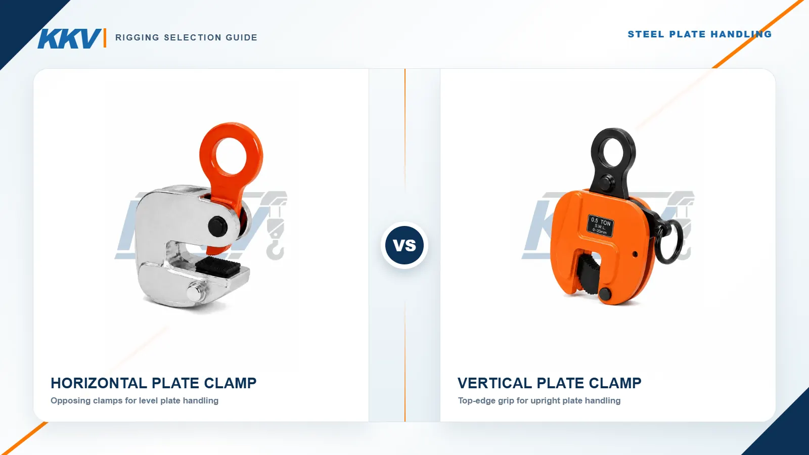
Horizontal vs Vertical Plate Lifting Clamps: Key Differences and How to Choose
Horizontal and vertical plate lifting clamps may look similar, but they control a steel plate in different orientations and rely on different rigging arrangements. A typical horizontal system grips opposing plate edges so the plate can be lifted and transferred approximately level. A basic vertical clamp grips near the upper edge so one plate can be raised, transferred or, only where the exact model permits it, turned between horizontal and vertical positions.
Selecting by tonnage alone is unsafe. The clamp must match the intended lifting direction, whether its working load limit applies to one clamp or a pair, the permitted minimum load, jaw range, plate material and hardness, surface condition, centre of gravity, sling geometry and inspection criteria. The load also has to be stable when it is first raised and throughout the planned travel.
Quick answer: Use horizontal plate clamps when the approved arrangement supports a plate from opposing sides and keeps it in a horizontal position. Use a vertical plate clamp when the approved model grips the plate from the upper edge for upright handling. In both cases, follow the exact nameplate, load diagram and manufacturer manual. Confirm whether the WLL is per clamp or per pair, verify plate thickness and minimum load, clean the gripping area, position the clamps around the centre of gravity, and make a short test lift before travelling.
Table of contents
- Horizontal vs Vertical Plate Lifting Clamps: The Short Answer
- What Is a Horizontal Plate Lifting Clamp?
- What Is a Vertical Plate Lifting Clamp?
- Horizontal vs Vertical Plate Lifting Clamps: Side-by-Side Comparison
- Capacity, Clamp Count and Load Distribution
- Plate Thickness, Surface and Jaw Compatibility
- Load Orientation, Plate Turning and Stability
- Inspection and Removal from Service
- How to Choose the Right Plate Lifting Clamp
- Information to Include in Your RFQ
- Frequently Asked Questions
Horizontal vs Vertical Plate Lifting Clamps: The Short Answer
The distinction begins with the load orientation, but it does not end there. Standard horizontal plate clamps are generally installed in opposing pairs or multiple pairs. Their lifting eyes are connected to a two-leg sling, chain assembly or spreader arrangement so the plate is supported at balanced positions. The listed WLL may be the capacity of the pair, not of each individual clamp. Multiplying a pair rating by two can therefore create a severe overload.
A basic vertical plate clamp is normally fitted over the upper edge of one plate. A cam or pivot presses the plate against the opposing jaw as lifting force is applied. Many vertical clamps include a lock or pre-tension mechanism that keeps the gripping components engaged during attachment and lowering. That mechanism does not make the clamp fail-safe and cannot compensate for an unsuitable plate, contaminated surface, wrong thickness, insufficient load or unauthorized side pull.
Some specialized vertical clamps are rated for turning a plate through 90 or 180 degrees, and some articulated designs permit loading from additional directions. Those capabilities are model-specific. A fixed-eye vertical clamp should not be treated as a universal turning clamp simply because another clamp has a similar body shape. Likewise, a horizontal clamp for one rigid plate should not be used for a bundle or a thin plate that will sag unless the manual expressly permits it.
The correct selection process is therefore:
- define the plate weight, size, material, surface and centre of gravity;
- decide the required orientation and whether any turning is necessary;
- select a clamp family specifically approved for that motion;
- check maximum WLL, minimum load, jaw range and hardness limits;
- confirm whether capacity is stated per clamp, per pair or per complete set;
- design the sling angles and clamp spacing from the applicable load diagram; and
- inspect, lock, test-lift and monitor the complete arrangement.
KKV’s current range includes HLC horizontal lifting clamps, LC horizontal lifting clamps and the CDH lifting clamp for vertical plate handling. The final choice must still be confirmed from the supplied model data and operating instructions.
What Is a Horizontal Plate Lifting Clamp?
A horizontal plate lifting clamp attaches to a plate edge so the plate can be lifted and moved in a generally horizontal position. In a common arrangement, two clamps are installed on opposite sides of the plate and connected to a two-leg sling. Longer or larger plates may require two opposing pairs connected through a spreader beam so the support points are distributed along the plate.
Many standard horizontal clamps use a cam, jaw or serrated gripping surface that develops force as the sling legs pull upward and inward. Other designs may use smooth or non-marking pads, special spring pre-tension or jaws intended for bending sheets. Product names alone do not establish those capabilities. The approved load type, gripping principle and restrictions must be read from the specific manual.
The HSE guidance on plate handling describes horizontal clamps as generally used in pairs and recommends multiple pairs with a spreader beam for larger sheets. Manufacturer guidance shows why the qualification matters: Terrier’s FHX/FHSX range is intended for a single non-deflecting plate, while its TDH range is designed for sheets that bend during lifting. Another specialized model may be approved for secured stacks. These permissions cannot be transferred between models.
Horizontal clamps are commonly selected when:
- the plate must remain horizontal during lifting and transfer;
- opposing edges are accessible and provide approved contact areas;
- clamp pairs can be placed symmetrically around the centre of gravity;
- the plate stiffness matches the clamp design;
- the sling or spreader arrangement follows the manufacturer’s load diagram; and
- the WLL, jaw opening and surface conditions match the actual load.
The current KKV HLC and LC pages state that their listed working load limits are based on paired operation. For those products, the pair rating must not be interpreted as the capacity of each clamp. Review the HLC product data or LC product data and confirm the complete set in the quotation.
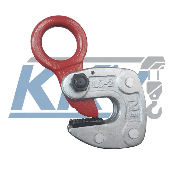
Horizontal handling still requires control of bending, rotation and slip. If the plate deflects, one pair may carry more load than expected or the clamp geometry may change. If the clamps are not opposite each other, the plate can rotate. If a sling leg is too short, increased angle and side force may overload the clamp or rigging. The arrangement should be designed before the clamp capacity is selected.
What Is a Vertical Plate Lifting Clamp?
A vertical plate clamp normally grips a plate near its top edge so the plate hangs upright. The plate is inserted fully into the jaw opening and a locking or pre-tension mechanism is placed in the specified position. As lifting force is applied, the cam or pivot develops grip against the plate. The lifting eye, cam, pivot, spring and lock form a system; damage or incorrect operation in any part can affect retention.
Standard vertical clamps are typically intended for one plate at a time. The Crosby IPU10 manual expressly requires one plate per lift for that family. A plate bundle may allow only the outside plate to be gripped while inner plates slide, so a bundle must not be lifted unless the exact clamp is designed and rated for it.
Some vertical clamps are rated for lifting, turning and transferring a plate through a defined range. Others are intended only for vertical lifting. An articulated lifting eye may allow the load line to change direction without side-loading the clamp body, but it can also have angle-related derating. A fixed lifting eye does not automatically have the same capability. Always distinguish among basic vertical, universal, hinged, turning and non-marking clamp designs.
Vertical clamps are commonly selected when:
- a single plate must be raised or transported in an upright position;
- the upper plate edge is accessible and can be fully inserted into the jaw;
- the load line is compatible with the clamp’s lifting-eye design;
- the material, surface hardness and finish match the gripping system;
- the plate load is above any specified minimum and below the maximum WLL; and
- the permitted turning operation, if any, is documented for the model.
The KKV CDH lifting clamp is the relevant current vertical-clamp product page. The product image shows a cam-style gripping assembly and lock mechanism, but capacity, jaw range, minimum load, hardness and allowable directions must be verified from the delivered model’s identification and documents rather than inferred from the image.
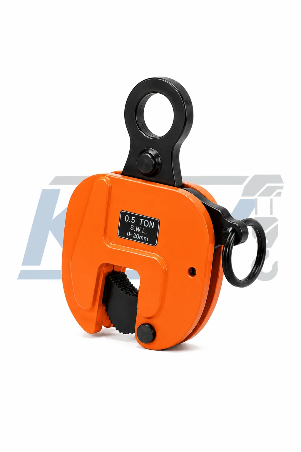
A safety lock helps maintain engagement during attachment and lowering, but it is not a substitute for lifting force and correct friction. The clamp should be fully seated, the gripping area clean, and the lock placed in the prescribed position before load is applied. Never use a handle, pipe or impact to force a clamp onto a plate outside its jaw range.
Horizontal vs Vertical Plate Lifting Clamps: Side-by-Side Comparison
This comparison describes typical arrangements. It is not a universal operating table. Specialized horizontal, vertical, universal, non-marking, bundle and turning clamps can differ substantially.
| Selection point | Horizontal plate lifting clamp | Vertical plate lifting clamp |
|---|---|---|
| Normal load orientation | Supports a plate in a generally horizontal position | Suspends a plate in a vertical position |
| Typical attachment | Opposing edges using a pair or multiple pairs | Upper plate edge using one or more approved clamps |
| Capacity basis | Frequently stated per pair; check the nameplate and table | Frequently stated per clamp, but set capacity and angle still require calculation |
| Load type | May be restricted to one rigid plate; sagging plate and bundles require special designs | Normally one plate at a time unless the manufacturer expressly permits otherwise |
| Jaw engagement | Opposing clamps must seat at balanced, approved contact points | Plate must be fully inserted so cam and opposing jaw engage correctly |
| Minimum load | Model-specific; do not assume zero minimum | Friction-type clamps often specify a minimum load, but the value is model-specific |
| Turning capability | Generally intended for horizontal transfer, not plate turning | Only turning-rated models may move between horizontal and vertical orientations |
| Sling geometry | Pair spacing, leg angle and spreader arrangement affect clamp force and load sharing | Load-line direction and lifting-eye articulation determine whether side loading is permitted |
| Primary stability concern | Unequal loading, plate bending, rotation and loss of opposite engagement | Side pull, insufficient grip, contaminated surface and unintended release during landing |
| Typical inspection focus | Body, jaw/cam, lifting eye, pins, paired condition and markings | Body, cam teeth, pivot, spring, lock, lifting eye, pins and markings |
Neither clamp type is inherently safer. A correctly selected horizontal pair can be unsafe if the plate sags or the pair WLL is misread. A correctly rated vertical clamp can be unsafe if the load is below its minimum requirement or the plate is harder than the jaw is designed to grip. Suitability depends on the complete conditions, not just the rated maximum capacity.
Regulatory and standards language should also remain precise. ASME B30.20 covers marking, inspection, testing, maintenance and operation of below-the-hook lifting devices. ASME BTH-1 provides design criteria. EN 13155 addresses non-fixed load lifting attachments including plate clamps. These documents do not replace the capacity chart or operating manual for an individual model.
Capacity, Clamp Count and Load Distribution
Begin with the maximum suspended load, including any spreader beam, lifting beam, sling assembly and fixtures carried by the crane hook. Confirm the plate’s centre of gravity rather than assuming it is at the geometric centre. Cut-outs, welded parts, varying thickness and attached components can shift it.
Next determine how many clamps will be used and what the marked WLL means. If a horizontal clamp is rated “2 t per pair,” the two-clamp set carries 2 t under the defined conditions; it is not a 4 t system. If a vertical clamp is rated per clamp, two clamps still do not automatically provide twice the capacity because sling angles, clamp spacing, plate stiffness and tolerances affect load sharing.
| Capacity input | Question to answer | Selection risk if ignored |
|---|---|---|
| WLL basis | Is the rating per clamp, per pair or per complete set? | Pair capacity may be accidentally doubled |
| Maximum suspended load | Does the total include beams, slings and fixtures? | Actual system load may exceed the selected WLL |
| Minimum permitted load | Does the clamp rely on a stated minimum load for gripping force? | A light plate may slip even though it is below maximum WLL |
| Clamp count | One, one pair, two pairs or another approved arrangement? | Unsupported assumptions about load sharing can overload one clamp |
| Centre of gravity | Where is the real balance point after all attachments are included? | The plate can tilt, rotate or unload a clamp |
| Clamp spacing | Are support points positioned to control bending and rotation? | Excessive deflection can change jaw and sling geometry |
| Sling angle | How is the angle defined in the manufacturer’s load diagram? | Greater sling tension or side force may exceed the permitted rating |
| Plate stiffness | Is the model approved for rigid plate, bending sheet or a bundle? | A standard clamp may disengage when the plate deflects |
For horizontal lifting, two short sling legs can create a wide included angle and large inward or side forces at the clamps. The correct maximum angle must come from the model load diagram, which must also state how the angle is measured. Do not publish or apply one universal 45- or 60-degree rule across all clamps.
When more than two clamps are used, a rigid equalizing or spreader arrangement may be needed. Four clamps connected to one hook through ordinary slings will not necessarily share 25 percent of the load each. Plate stiffness, fabrication tolerances, sling length and centre-of-gravity offset can put much more load on one or two points. A qualified person should determine the arrangement and allowable set capacity.
For vertical lifting, maximum WLL is only one boundary. Many friction-type clamps specify a minimum load, sometimes expressed as a percentage of maximum WLL. That percentage is not universal and can change with clamp size, plate hardness or specialized construction. A light plate may therefore require a smaller clamp even when a larger clamp appears to provide more reserve capacity.
Plate Thickness, Surface and Jaw Compatibility
Measure the actual plate thickness at the intended gripping location. It must fall within the model’s permitted jaw range, including both any minimum and maximum limit. The jaw should open and close normally without forcing, and the plate must enter to the full required depth. Gripping only the tip of a plate can damage teeth, reduce contact and allow the plate to escape.
Material is equally important. Standard cam-and-pivot clamps are often designed for a stated range of carbon-steel hardness. High-strength or hardened steel may prevent the teeth from penetrating or developing the required grip. Stainless steel can require dedicated components to avoid contamination and to match different surface properties. Aluminum, coated plate, polished material and non-marking work may require a completely different clamp principle.
Do not assume that a wide jaw range makes a clamp suitable for every material within that thickness. Confirm:
- plate material and grade;
- surface hardness at the contact area;
- actual thickness and whether it varies;
- flat, parallel contact surfaces or any taper and curvature;
- paint, galvanizing, scale, corrosion, oil, water, ice or other contamination;
- whether tooth marks are acceptable; and
- whether the supplier permits that material and finish.
The gripping area should be free from oil, grease, moisture, ice, loose mill scale, dirt and coatings that interfere with the intended contact. Cleaning must follow the manufacturer’s directions; do not grind away a coating or alter the clamp teeth to create grip. If the plate cannot be safely cleaned or marked, select a purpose-designed non-marking or alternative lifting method.
KKV’s horizontal products have different published jaw ranges by model and capacity. Compare the LC horizontal clamp and HLC horizontal clamp tables against the measured plate. Do not transfer a jaw figure from one family to another.
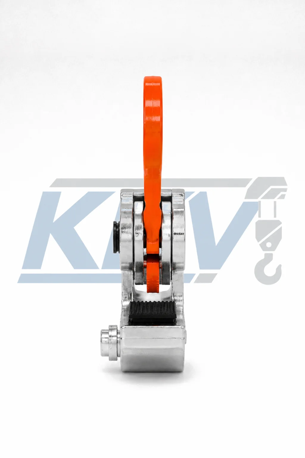
The PDB lifting clamp page includes a broad capacity range, but its current public descriptions are not consistent about lifting direction and its largest size lacks complete jaw and net-weight data. Until product-specific manufacturer documentation resolves those points, ask KKV to confirm the intended orientation and exact specifications in writing rather than inferring them from the page title or product image.
Load Orientation, Plate Turning and Stability
Plan the entire movement: attachment, initial tension, lift-off, travel, any rotation, landing and clamp release. A clamp that can hold a stationary vertical plate may not be rated to pick a plate from flat, turn it through 90 degrees and lay it down again. Turning moves the centre of gravity relative to the clamp, changes the lifting-eye direction and can create side load.
Use only a model whose manual expressly allows the required motion. If the model permits turning, follow its specified orientation, load diagram and ground-contact sequence. Some instructions require the plate to remain supported while it is rolled through part of the motion. Do not let the clamp or load strike an obstacle because impact or temporary unloading can release tension and change jaw engagement.
Horizontal arrangements must control plate rotation and deflection. Place paired clamps symmetrically around the centre of gravity and as directed for the model. Longer plates may need two pairs and a spreader beam. Keep sling legs long enough to satisfy the load diagram, and verify that lifting eyes align with the intended force instead of being twisted or pressed sideways.
Before travelling, perform a short test lift:
- Clear personnel from the load and travel area.
- Take up slack slowly while observing clamp seating and sling alignment.
- Raise the plate only a short distance from its support.
- Stop and check balance, jaw engagement, lock position and load sharing.
- Lower and correct the rigging if the plate tilts unexpectedly or any clamp shifts.
- Continue only after the arrangement is stable and the travel path is clear.
A test lift is an operational check, not a proof test and not evidence that an unsuitable clamp has become acceptable. Keep people away from the suspended load, never stand below it, avoid shock loading, and move smoothly. HSE’s safe lifting guidance requires lifting operations to be properly planned, supervised and carried out safely.
Inspection and Removal from Service
The operator should inspect the clamp before each use in accordance with the manual and site procedure. A competent person should also perform the required periodic examination. Under UK LOLER guidance, lifting accessories are generally thoroughly examined at six-month intervals unless a competent person’s written examination scheme establishes another interval; other jurisdictions may differ.
Clean the clamp enough to see and operate all critical parts. Do not conceal defects with paint or grease. Compare components with the manufacturer’s acceptance limits, not an improvised percentage. Jaw and tooth wear limits vary by model.
| Inspection point | Check before use | Remove or quarantine when |
|---|---|---|
| Identification | WLL, jaw range, model and serial information are legible | Identity or operating limits cannot be confirmed |
| Clamp body | No cracks, bends, heat damage, corrosion or deformation | Any defect could affect the load path or indicates overload |
| Cam, pivot and jaw | Clean, sharp as specified, correctly aligned and within wear limits | Teeth are chipped, rounded beyond limits, cracked or damaged |
| Lifting eye or shackle | Moves as designed and shows no twist, elongation or abnormal wear | Eye is distorted, cracked, seized or worn beyond the manual limit |
| Pins and fasteners | Secure, correctly retained and not visibly worn | Missing, loose, bent or damaged components are found |
| Spring and lock | Operate freely and return or latch as specified | Lock will not hold, spring action is weak, or movement is stiff |
| Jaw opening | Opens and closes through its intended range | Operation is forced, seized or cannot fully engage the plate |
| Paired set | Correct matching models, capacities and compatible condition | Clamps are mismatched or one unit is damaged |
Remove the clamp from service after overload, shock loading, a dropped load or other abnormal event until a competent person evaluates it. Do not straighten a bent body, grind teeth, heat components, weld cracks or substitute pins in the field. Repairs and proof testing must follow the manufacturer’s approved process and applicable rules.
Store clamps where jaws and mechanisms are protected from impact, moisture and contamination. Keep inspection and repair records as required. The HSE’s thorough examination guidance distinguishes routine pre-use checks from the systematic examination performed by a competent person; one does not replace the other.
How to Choose the Right Plate Lifting Clamp
Use a repeatable sequence rather than beginning with the catalogue capacity.
Step 1: Define the Plate
Record maximum mass, length, width, thickness, material grade, hardness, surface finish and stiffness. Mark the centre of gravity and identify safe gripping areas. State whether tooth marks are acceptable and whether paint, coating or contamination is present.
Step 2: Define the Required Motion
State the starting and finishing orientations. Decide whether the plate must remain horizontal, hang vertically or be turned. Include pickup height, landing method, travel route and clearances. If turning is required, select a model explicitly approved for that rotation.
Step 3: Select the Clamp Principle
Choose an approved horizontal pair or multiple-pair arrangement for level handling. Choose an appropriate vertical or universal clamp for upright lifting. Use a non-marking design only when its material, pad condition and load limits fit the application. Do not repurpose a similarly shaped clamp.
Step 4: Verify Capacity Boundaries
Confirm whether WLL is per unit or per pair, the maximum load, any minimum load, jaw range, material hardness and temperature restrictions. Include the weight of spreader beams and rigging. Apply manufacturer angle or direction reductions where required.
Step 5: Design Clamp Positions and Rigging
Place clamps relative to the real centre of gravity. Determine the number of points, spacing, sling lengths, included angles and any equalizing beam. Check every lifting eye, link, shackle and sling for fit and capacity. Do not assume equal load sharing without a justified arrangement.
Step 6: Confirm Documentation and Inspection
Specify the applicable standard, identification, declaration or test certificate, manual and traceability required by the project. Establish pre-use inspection, periodic examination, quarantine, maintenance and storage responsibilities before the equipment arrives.
Step 7: Attach and Test-Lift
Clean contact areas, insert the plate fully, operate the lock and connect the rigging as instructed. Take up slack without shock. Make a short test lift, confirm balance and seating, then proceed only when the complete system is stable.
If any required input is unknown, pause selection. A conservative-looking larger clamp is not automatically safer because it may have a higher minimum load, larger jaw geometry or different gripping components. The safest model is the one whose complete operating envelope matches the plate and lift plan.
Information to Include in Your RFQ
Send enough information for the supplier to select the clamp and confirm the arrangement:
- horizontal, vertical or turning application;
- maximum and minimum plate weight;
- plate length, width and actual thickness range;
- material grade and surface hardness;
- coating, paint, oil, scale, moisture or other surface conditions;
- whether tooth marks are acceptable;
- one plate, flexible sheet, rigid plate or secured bundle;
- required number of clamps and whether WLL must be per pair or per unit;
- starting orientation, final orientation and turning angle;
- centre-of-gravity location and proposed clamp positions;
- sling-leg lengths, angle convention, spreader beam and connected hardware;
- indoor or outdoor environment and temperature;
- required standard, certificate, declaration, manual and inspection record;
- quantity, destination and packaging requirements; and
- photographs or a drawing of the plate and complete load path.
For horizontal handling, compare the KKV HLC and KKV LC ranges, remembering that their current pages state capacity on a paired basis. For vertical handling, review the KKV CDH page and request the exact model’s minimum load, jaw and direction limits. The lifting clamp category shows the currently published range.
Do not request only “two 2-ton clamps.” That phrase does not establish whether 2 tons is per clamp or per pair, whether the plate is heavy enough to develop grip, or whether the jaws fit the material. A clear RFQ allows those questions to be answered before delivery rather than at the crane hook.
Frequently Asked Questions
What is the main difference between horizontal and vertical plate clamps?
A horizontal clamp system normally grips opposing plate edges so the plate remains approximately level. A vertical clamp grips the upper plate edge so the plate hangs upright. Specialized models may turn, handle flexible sheet or grip without marking, but those capabilities must be stated for the exact model.
Are horizontal plate clamps always used in pairs?
They are generally used in opposing pairs or multiple pairs in standard plate-handling applications. Some specialized lifting devices may use another arrangement. Follow the product load diagram and confirm whether the WLL is given per pair or per unit.
If a horizontal clamp is rated 2 tons per pair, can two clamps lift 4 tons?
No. “2 tons per pair” means the complete two-clamp pair is rated for 2 tons under the specified conditions. Treating each clamp as 2 tons would double the intended set load. KKV’s current HLC and LC pages state that their listed WLL is based on paired operation.
Can I use a larger-capacity clamp for a very light plate?
Not automatically. A friction-type clamp may have a minimum permitted load. If the plate is too light, the gripping force may be insufficient even though it is far below maximum WLL. Check the exact model’s minimum-load rule and hardness conditions.
Can one vertical clamp lift several plates together?
Normally no. Standard vertical clamp instructions commonly require one plate per lift because only the outside plate may be gripped. Use a bundle-rated device only when the manufacturer expressly approves the plate package and arrangement.
Can every vertical plate clamp turn a plate through 180 degrees?
No. Turning capability depends on the lifting-eye design, cam system, load direction and model rating. Use only a clamp whose manual specifically permits the required turning sequence and follow its load diagram and ground-contact instructions.
Does plate thickness only need to be below the maximum jaw opening?
No. Thickness must be within the complete permitted range, including any minimum. The plate must also be fully inserted, the contact surfaces appropriate, and the load within the allowed maximum and minimum. A partially seated thin plate can still be unsafe.
Can plate clamps be used on painted, oily or hardened steel?
Only if the exact model is approved for that material and surface. Oil, paint, loose scale, moisture and ice can interfere with gripping. Hardened steel, stainless steel and non-marking applications frequently require specialized jaw materials or clamp designs.
How many clamps are needed for a long steel plate?
It depends on plate length, stiffness, mass, centre of gravity and the manufacturer’s permitted arrangement. Large or long plates often require two pairs and a spreader beam. A qualified person should determine spacing and load distribution; four clamps do not automatically share the load equally.
What information should I send KKV for a quotation?
Provide plate weight, dimensions, thickness range, material, hardness, surface condition, lifting orientation, turning requirement, centre of gravity, clamp count, sling geometry, environment and documentation needs. Include photographs or a load-path drawing, then contact KKV for a model-specific recommendation.
Select the Clamp for the Complete Lifting Plan
The correct question is not simply whether a horizontal or vertical clamp has enough tonnage. The question is whether the exact clamp and complete rigging arrangement control the actual plate throughout attachment, lift-off, travel, any turning and landing.
Use the HLC or LC horizontal clamp only with a confirmed paired arrangement and compatible plate. Use the CDH vertical clamp only after verifying the delivered model’s WLL, minimum load, jaw range, plate hardness and permitted lifting directions. For the PDB clamp, obtain written confirmation of the applicable lifting direction and complete specification before selection.
For a plate-clamp quotation, contact KKV or email sales@kkvhoist.com with the plate weight, dimensions, thickness, material, surface, required orientation, clamp arrangement, sling geometry and documentation requirements.
Safety note: This article is general selection information. It is not a lift plan, engineering calculation, inspection report or substitute for the clamp nameplate, manufacturer manual, applicable law, site procedure or a competent person’s assessment. Do not exceed WLL, ignore minimum-load requirements, modify a clamp or stand beneath a suspended plate.