HLC Horizontal Lifting Clamp
The HLC Horizontal Lifting Clamp is a
horizontal plate clamp designed for lifting and transferring
steel plates in pairs with stable gripping performance.
- Rated capacity range from 1T to 3T.
- Suitable for horizontal lifting and transfer of steel plates.
- Lightweight body with strong structural durability.
- Durable gripping structure for plate handling applications.
- WLL is based on clamp pair operation.
- Suitable for fabrication, construction and workshop lifting.
Description
HLC Horizontal Lifting Clamp for Steel Plate Handling
The HLC Horizontal Lifting Clamp is a compact
plate-handling clamp designed for horizontal lifting and
transfer of suitable steel plates.
The clamp is intended for paired or suitable multi-clamp
lifting arrangements so that the load can be supported in
a stable horizontal position. Its compact construction helps
simplify positioning and handling.
The current KKV specification range covers
1T, 2T and 3T, with jaw openings from
0–15 mm to 0–30 mm.
Compact Horizontal Plate Lifting in Paired Operation
Horizontal Plate Handling
Designed for horizontal lifting and transfer
of suitable steel plates.
Paired Operation
Used in pairs or suitable multi-clamp arrangements
to maintain load balance.
Compact Design
The compact clamp form simplifies positioning
around suitable plate edges.
Lightweight Handling
Low unit weight relative to capacity helps
simplify clamp positioning.
Durable Steel Body
The clamp body and load-bearing components
are designed for industrial plate handling.
1T–3T KKV Range
Available in three rated capacities with
model-specific jaw-opening ranges.
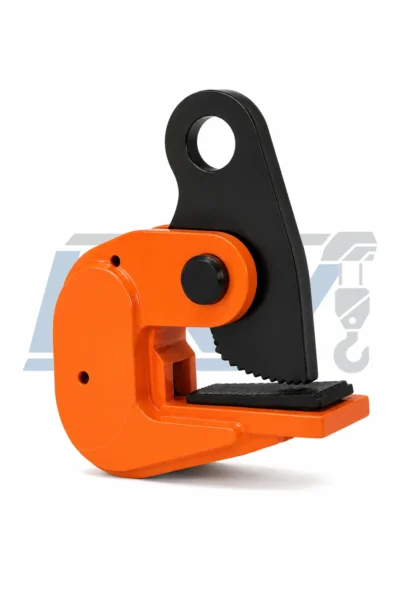
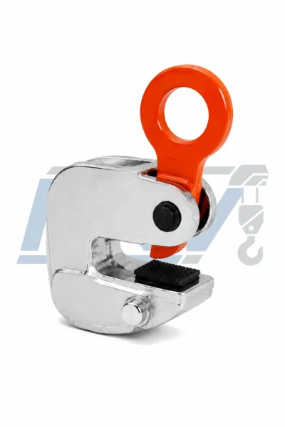
HLC Horizontal Lifting Clamp Construction Details
The product images are grouped into one balanced 2×2
presentation so the overall clamp, side profile,
gripping area and lifting connection can be compared
without repetitive standalone images.
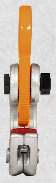
Complete Clamp Assembly
The complete HLC structure combines the
lifting eye, clamp body and load-contact
components in a compact form.
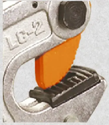
Compact Side Profile
The low-profile design helps simplify
positioning around suitable steel plate edges.
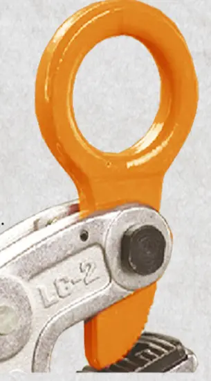
Durable Load-Contact Area
The load-contact surfaces are designed to
support stable engagement during the intended
horizontal lifting arrangement.
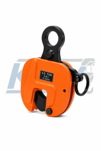
Lifting Eye & Product Details
The lifting eye provides the rigging connection,
while visible product details support model
and capacity identification.
Support the Load with a Balanced Clamp Arrangement
Horizontal plate clamps should be arranged so the load
remains balanced throughout the lifting operation.
Position each clamp correctly and confirm the complete
rigging arrangement before applying load.
Place clamps so the load is supported evenly
on both sides.
Select the correct clamp capacity for the
complete lifting arrangement.
Verify that the actual plate thickness fits
within the listed range.
Apply lifting force smoothly and maintain
stable rigging throughout the lift.
HLC Horizontal Lifting Clamp Applications
Steel Plate Handling
Horizontal lifting and transfer of suitable
steel plate materials.
Fabrication Workshops
Moving steel plates between cutting,
welding and assembly operations.
Construction Handling
Controlled horizontal handling of suitable
steel components during construction work.
Material Storage
Plate positioning during loading, unloading
and storage operations.
How to Select an HLC Horizontal Lifting Clamp
Determine Required Capacity
Select the clamp size according to the complete
lifting load and rigging arrangement.
Measure Plate Thickness
Confirm that the steel plate fits within
the listed jaw-opening range.
Plan Pair Positioning
Arrange clamps so the load remains balanced
and stable in the horizontal position.
Confirm Rigging Geometry
Use appropriate slings or lifting hardware
for the selected clamp arrangement.
Inspect Contact Surfaces
Verify that each clamp can seat and engage
correctly before applying load.
Inspect the HLC Clamp Set Before Use
deformation or abnormal wear.
correctly matched to the operation.
applying the load.
capacity remain legible.
the lifting set is used again.
Need Help Selecting the Right HLC Clamp?
Compare rated capacity, jaw opening, plate thickness
and paired lifting arrangement before selecting your
HLC Horizontal Lifting Clamp.
Additional information
| Rated Capacity | 1T–3T |
|---|---|
| Jaw Opening | 0–15 / 0–20 / 0–30 mm |
| Lifting Arrangement | Used in Pairs |
HLC Horizontal Lifting Clamp Technical Specifications
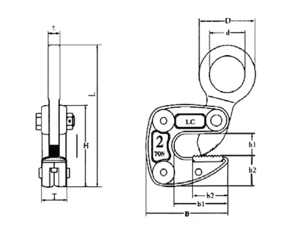
Compare rated capacity, net weight, jaw opening and package details before selecting the appropriate HLC Horizontal Lifting Clamp.
| Model | Rated Capacity | Net Weight (kg) | Jaw Opening | Package |
|---|---|---|---|---|
| HLC Horizontal Lifting Clamp | 1T | 2.1 | 0–15 mm | 8 pcs/carton |
| 2T | 5.6 | 0–20 mm | 4 pcs/carton | |
| 3T | 8 | 0–30 mm | 4 pcs/carton |
Selection Note: Confirm rated capacity, plate thickness, jaw opening and the complete horizontal lifting arrangement before ordering.