GCL-B Geared Trolley
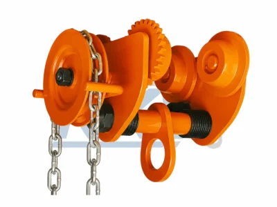
The GCL-B Geared Trolley is a hand-chain operated
beam trolley designed for controlled horizontal travel of hoists
and suspended loads along compatible I-beams.
- Rated capacity range from 0.5T to 20T.
- Hand-chain geared travel for controlled load positioning.
- Precision chain guide system for smooth chain engagement.
- Sealed bearing wheel assemblies for reliable beam travel.
- Anti-drop structure for improved trolley security.
- Adjustable spacer system for different I-beam flange widths.
- Reinforced central suspension eye for compatible lifting hoists.
Description
GCL-B Geared Trolley for Controlled I-Beam Travel
The GCL-B Geared Trolley is designed for
controlled horizontal movement of hoists and suspended loads
along compatible I-beams using a manually operated
hand-chain gear drive.
The geared travel mechanism allows the operator to move the
trolley without directly pushing the suspended load, making
the GCL-B suitable for industrial lifting applications where
controlled positioning and convenient operation are required.
Available in capacities from 0.5T to 20T,
the trolley combines sealed wheel assemblies, adjustable
beam spacing, steel structural components and a reinforced
central suspension connection.
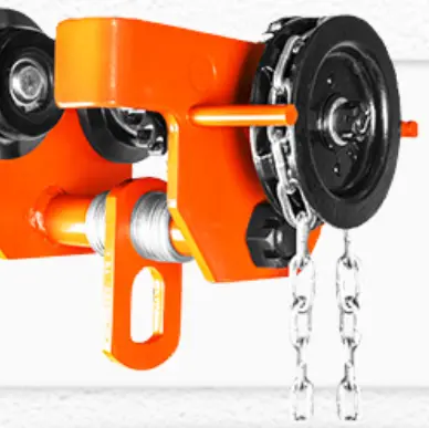
Geared Hand-Chain Travel with Reinforced Construction
Hand-Chain Geared Travel
The hand-chain mechanism transfers operator input
through the gear drive for controlled horizontal
trolley movement.
Precision Chain Guide
The chain guide arrangement helps maintain smooth
engagement between the operating hand chain and
the geared drive wheel.
Sealed Bearing Wheels
Sealed bearing wheel assemblies support stable,
low-resistance travel along compatible beam flanges.
Anti-Drop Structure
Anti-drop structural components provide additional
protection around the trolley and beam connection.
Adjustable Beam Fit
Spacer collars allow the trolley width to be
configured for different compatible I-beam
flange dimensions.
Reinforced Suspension Eye
The central steel suspension structure provides
a strong connection point for compatible hoists
and lifting equipment.
Key GCL-B Geared Trolley Construction Details
The GCL-B combines a geared hand-chain drive, precision wheel
assemblies, adjustable spacing and a reinforced suspension
structure for controlled beam travel.

Precision Chain Guide
The chain guide wheel helps maintain consistent
hand-chain engagement during geared trolley travel.
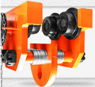
Geared Drive Assembly
The mechanical gear system transfers hand-chain
movement into controlled trolley wheel rotation.
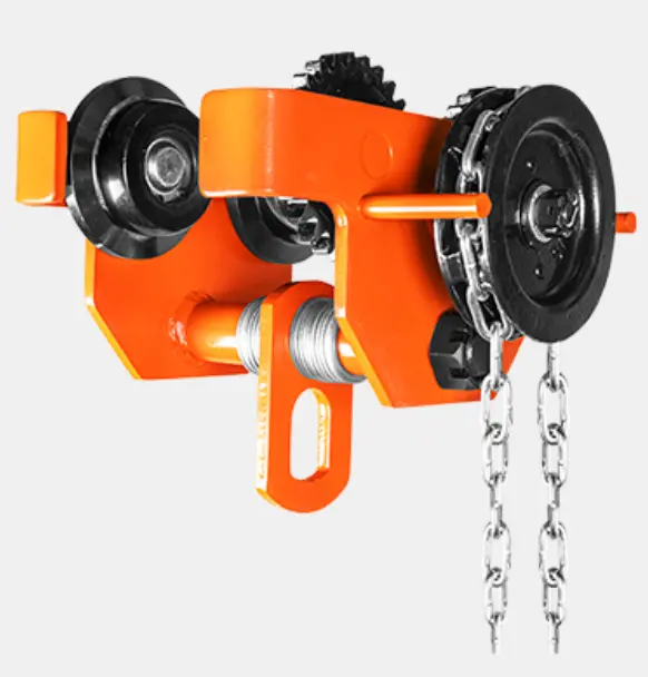
Reinforced Suspension Eye
The thickened central steel suspension point provides
a dedicated connection between the trolley and
compatible lifting hoists.
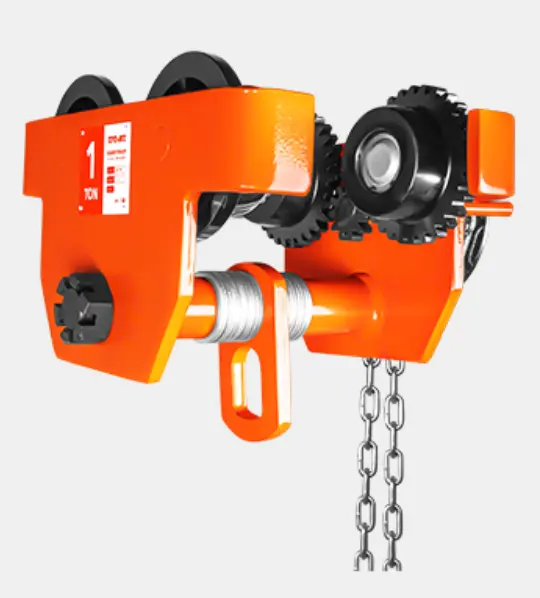
Adjustable Spacer System
Spacer collars allow the distance between the trolley
side assemblies to be adjusted for the actual beam width.
Controlled Horizontal Positioning by Hand Chain
Instead of directly pushing the suspended load, the
GCL-B uses a geared hand-chain mechanism
to control horizontal travel along the beam.
Pulling the operating chain rotates the drive wheel and gear
assembly, transferring manual input to the trolley wheels.
This provides more deliberate load positioning while retaining
a fully mechanical travel system.
Hand-Chain Control
The operator controls horizontal trolley movement
through the operating hand chain.
Mechanical Gear Drive
Gear transmission converts chain movement into
controlled wheel rotation.
Controlled Positioning
Suitable where more deliberate movement is required
than with a manually pushed plain trolley.
No Electric Travel Motor
Horizontal travel is mechanically operated without
requiring a powered trolley motor.
Stable Beam Travel with Protected Wheel Assemblies
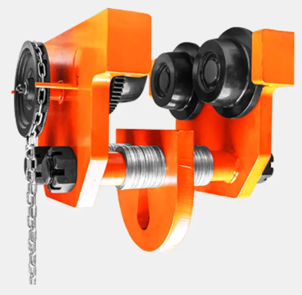
Sealed Bearing Wheel
Sealed bearing assemblies support smooth wheel
rotation while helping protect the internal
bearing area during normal industrial use.

Anti-Drop Protection
Structural anti-drop components provide additional
trolley retention around the beam-running assembly.
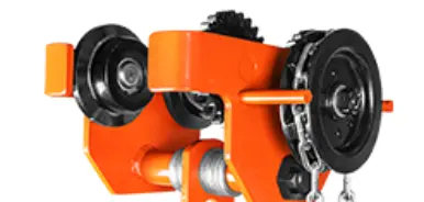
Hand Chain & Drive Wheel
The operating chain engages with the drive wheel
to transmit manual pulling force into trolley travel.
Adjust the GCL-B to the Actual I-Beam Width
Correct beam adjustment helps maintain suitable wheel
positioning and smooth geared travel. Confirm the actual
beam flange width before trolley installation.
Measure the Beam
Confirm the actual I-beam flange width
before configuring the trolley.
Adjust the Collars
Arrange the spacer collars to obtain the
required trolley width for the selected beam.
Center the Suspension
Keep the suspension point centered relative
to both trolley wheel assemblies.
Test Geared Travel
Pull the operating chain and confirm smooth
wheel and gear movement before applying load.
GCL-B Geared Trolley Construction from Multiple Angles

Trolley Assembly
The compact assembly integrates the wheel system,
geared travel mechanism and central suspension structure.

Complete Geared Travel System
Wheel, gear, hand-chain and suspension components
work together as one manually operated trolley system.
GCL-B Geared Trolley Applications
Industrial Workshops
Controlled horizontal positioning of suspended
hoists and loads along workshop beams.
Machinery Installation
Suitable for moving and positioning equipment
during installation and assembly work.
Maintenance Systems
Controlled beam travel for lifting operations
during machinery maintenance and repair.
Warehouse Handling
Manual geared travel for suspended loads
along compatible fixed I-beam systems.
How to Select a GCL-B Geared Trolley
01
Confirm Load Capacity
Select a trolley with sufficient rated
capacity for the maximum intended load.
02
Measure Beam Width
Confirm that the beam flange width falls
within the applicable trolley adjustment range.
03
Check Turning Radius
For curved beam systems, compare the required
radius with the listed minimum turning radius.
04
Check Hand-Chain Access
Confirm that the operating chain can be
reached safely from the intended operating position.
05
Match the Hoist
Confirm compatibility between trolley capacity,
hoist capacity and the complete suspension system.
Inspect the GCL-B Before Operation
excessive wear or damaged links.
before operating the trolley.
wear, looseness or restricted rotation.
suspension structure for visible damage.
configured for the installed beam.
gear, chain and wheel movement before lifting.
Need Help Selecting the Right Geared Trolley?
Compare rated capacity, I-beam width, minimum turning
radius, hand-chain operation and trolley dimensions
before selecting your GCL-B Geared Trolley.
Coming Soon
Additional information
| Rated Capacity | 0.5–20T |
|---|---|
| I-Beam Width | 68–203mm |
| Min. Turning Radius | 0.9–5.0m |
GCL-B Geared Trolley Technical Specifications
Compare rated capacity, compatible I-beam width, minimum turning radius, net weight and trolley dimensions before selecting the appropriate GCL-B Geared Trolley.
| Capacity |
I-Beam Width (mm) |
Minimum Turning Radius |
Net Weight (kg) |
A (mm) |
B (mm) |
C (mm) |
H (mm) |
|---|---|---|---|---|---|---|---|
| 0.5T | 68–94 | 0.9 m | 5.3 | 189 | 170 | 183 | 112 |
| 1T | 68–100 | 1.0 m | 7.5 | 208 | 193 | 215 | 143 |
| 2T | 94–124 | 1.1 m | 11.2 | 250 | 235 | 260 | 175 |
| 3T | 116–140 | 1.3 m | 21 | 288 | 280 | 308 | 215 |
| 5T | 140–180 | 1.4 m | 30.5 | 355 | 335 | 382 | 250 |
| 10T | 125–180 | 1.7 m | 90 | 362 | 395 | 510 | 295 |
| 20T | 136–203 | 5.0 m | 235 | 475 | 642 | 622 | 315 |
Selection Note: Confirm trolley capacity, I-beam flange width, required turning radius and installation dimensions before ordering. Actual beam dimensions and operating conditions should always be verified before installation.