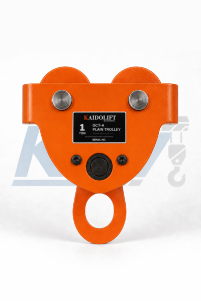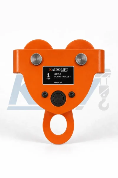



GCT-B plain trolley
The GCT-B Plain Trolley is a manually operated
beam trolley designed for smooth horizontal movement of hoists
and suspended loads along compatible I-beams.
- Rated capacity range from 0.5T to 20T.
- Manual push travel without an electric drive motor.
- Precision guide wheels for smooth beam travel.
- Reinforced steel side-plate construction.
- Adjustable spacer system for different I-beam flange widths.
- Reinforced central suspension eye for compatible hoists.
- Suitable for workshops, warehouses and industrial lifting systems.
Description
GCT-B Plain Trolley for Industrial I-Beam Travel
The GCT-B Plain Trolley is designed for
manual horizontal movement of hoists and suspended loads
along compatible I-beams. Its reinforced steel structure,
precision wheel assemblies and adjustable beam fit provide
a practical trolley solution for industrial lifting systems.
Available in capacities from 0.5T to 20T,
the GCT-B can be adjusted for different beam flange widths
and used together with compatible chain hoists and other
lifting equipment for controlled load positioning.

Reinforced Construction for Stable Manual Travel
Precision Guide Wheels
The wheel assemblies support smooth manual travel
along compatible I-beam flanges while maintaining
stable trolley positioning.
Reinforced Steel Plates
Structural steel side plates form a rigid trolley
frame and support the wheel, axle and suspension
components.
Adjustable Beam Fit
Spacer washers allow trolley width to be adjusted
according to the required I-beam flange dimension.
Reinforced Suspension Eye
The central suspension point provides a strong
connection location for compatible lifting hoists.
Four-Wheel Support
The wheel arrangement distributes trolley support
across both sides of the beam for controlled travel.
Manual Operation
Simple push travel eliminates the need for a
dedicated trolley motor or geared travel mechanism.
GCT-B Plain Trolley Structural Details
Key trolley components are designed around stable beam travel,
adjustable installation and a reliable suspension connection.

Precision Guide Wheel
The wheel profile is designed for smooth contact
with the compatible beam flange during manual travel.

Reinforced Steel Structure
Formed steel side plates provide the primary
structural support for the trolley assembly.
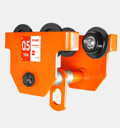
Adjustable Spacer System
Spacer washers allow the distance between the
trolley side assemblies to be configured for
different beam widths.
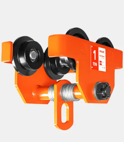
Reinforced Suspension Eye
The central lifting connection provides a
dedicated suspension location for compatible hoists.
Built Around the Main Load-Carrying Components
The GCT-B uses a straightforward mechanical construction
so that the primary trolley components remain easy to inspect,
adjust and maintain during normal service.
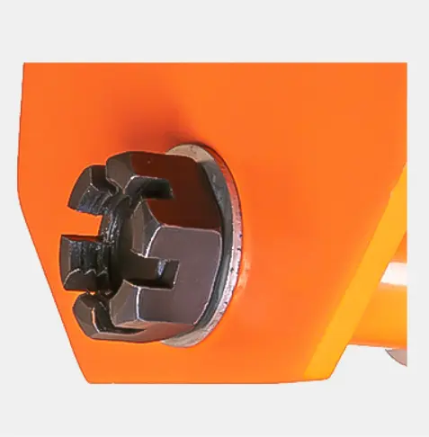
Wheel & Bearing Area
The wheel assembly supports trolley movement
while maintaining alignment along the beam.

Beam Width Adjustment
Adjustable spacing components help match the
trolley configuration to the selected beam flange.

Side Plate Assembly
The side plates connect the wheel and axle
components into a compact trolley frame.

Suspension Assembly
The central suspension structure transfers
the suspended hoist load into the trolley frame.
Simple Push Travel for Horizontal Load Positioning
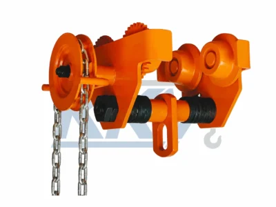
The GCT-B is a plain trolley.
Horizontal travel is therefore produced manually instead
of through a geared hand chain or electric travel motor.
This configuration is particularly suitable where loads
only need controlled horizontal movement over relatively
short distances along a fixed beam.
Manual Push Travel
Horizontal movement is produced by manually
moving the suspended trolley system.
No Travel Motor
No dedicated electrical drive is required
for trolley movement.
Compact Construction
A straightforward mechanical layout reduces
unnecessary travel components.
Practical Positioning
Suitable for workshop, maintenance and
general industrial load positioning.
Adjust the GCT-B to the Actual I-Beam Width
Correct trolley adjustment is important for stable wheel travel.
Before installation, confirm the actual beam flange width and
select the corresponding trolley capacity and adjustment range.
Measure the Beam
Measure the actual I-beam flange width before
configuring the trolley.
Adjust the Spacers
Arrange the spacer washers to obtain the
required trolley width.
Center the Suspension
Keep the suspension point correctly centered
relative to both wheel assemblies.
Verify Wheel Clearance
Confirm smooth wheel travel and suitable
clearance before applying the working load.
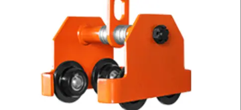
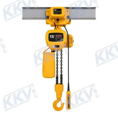
Reinforced Central Connection for Compatible Hoists
The GCT-B central suspension point provides the connection
between the trolley and compatible chain hoists or other
lifting equipment.
The trolley and hoist should be selected as a complete
lifting system, with the rated capacity of every component
suitable for the maximum intended load.

GCT-B Plain Trolley Applications
Industrial Workshops
Manual travel of suspended hoists and loads
along compatible workshop beam systems.
Machinery Installation
Horizontal positioning of machinery and equipment
during installation and maintenance operations.
Warehouse Handling
Suitable for controlled load positioning
along fixed overhead I-beam systems.
Maintenance & Repair
Practical trolley travel for lifting systems
used during equipment servicing and repair.
How to Select a GCT-B Plain Trolley
01
Confirm Load Capacity
Select a trolley with sufficient rated capacity
for the maximum intended suspended load.
02
Measure Beam Width
Confirm that the I-beam flange width falls
within the applicable trolley adjustment range.
03
Check Turning Radius
For curved beam systems, compare the required
curve with the listed minimum turning radius.
04
Match the Hoist
Confirm compatibility between trolley capacity,
hoist capacity and the suspension arrangement.
05
Review Operating Conditions
Consider travel distance, beam condition and
the actual working environment before selection.
Inspect the GCT-B Before Operation
rotate freely without abnormal resistance.
structure for visible deformation or damage.
remains correctly adjusted to the installed beam.
are properly positioned before operation.
and confirm smooth travel before lifting.
structural damage or insecure components are identified.

Need Help Selecting the Right GCT-B Plain Trolley?
Compare rated capacity, I-beam width, minimum turning
radius and trolley dimensions before selecting the
appropriate GCT-B for your lifting system.
Coming Soon
Additional information
| Rated Capacity | 0.5–20T |
|---|---|
| I-Beam Width | 68–203mm |
| Min. Turning Radius | 0.9–5.0m |
GCT-B Plain Trolley Technical Specifications
Compare rated capacity, compatible I-beam width, minimum turning radius, net weight and trolley dimensions before selecting the appropriate GCT-B Plain Trolley.
| Capacity |
I-Beam Width (mm) |
Minimum Turning Radius |
Net Weight (kg) |
A (mm) |
B (mm) |
C (mm) |
H (mm) |
|---|---|---|---|---|---|---|---|
| 0.5T | 68–94 | 0.9 m | 5.3 | 189 | 170 | 183 | 112 |
| 1T | 68–100 | 1.0 m | 7.5 | 208 | 193 | 215 | 143 |
| 2T | 94–124 | 1.1 m | 11.2 | 250 | 235 | 260 | 175 |
| 3T | 116–140 | 1.3 m | 21 | 288 | 280 | 308 | 215 |
| 5T | 140–180 | 1.4 m | 30.5 | 355 | 335 | 382 | 250 |
| 10T | 125–180 | 1.7 m | 90 | 362 | 395 | 510 | 295 |
| 20T | 136–203 | 5.0 m | 235 | 475 | 642 | 622 | 315 |
Selection Note: Confirm trolley capacity, I-beam flange width, required turning radius and installation dimensions before ordering. Actual beam dimensions and operating conditions should always be verified before installation.